PAGE: 210
MAR 30/2020
INSTALLATION MANUAL OPERATION MANUAL
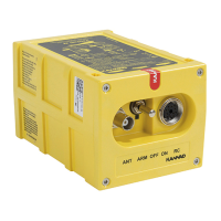
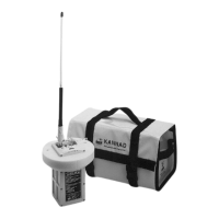
KANNAD 406 AF / AF-H / AF (6D)
© 2020 Orolia S.A.S. All rigths are strictly reserved.
The proximity of the ELT antenna to any vertically-polarized communications
antenna shall be such as to minimize radio frequency interference and radiation
pattern distorsion of either antenna. Coaxial cable connecting the ELT antenna
installation should not cross the aircraft production breaks and should have
vibrations proof RF connectors on each end. The coaxial connecting the ELT
transmitter to the external Antenna should be secured to the aircraft structure
and when the coaxial cable is installed and the connectors are mated, each end
should have some slack."
B. Antenna installation procedure
The antenna must be mounted on the top of the aircraft to assure maximum
visibility of satellites. The upper aft portion of the fuselage should be preferred.
It should be mounted away from projections such as a propeller, tail surfaces,
or the shadow of large antennas. It is the responsibility of the installation
agency to determine the appropriate and adequate antenna installation.
Locate a position on the fuselage according to § (2) RTCA DO-204
Requirements for ELT location page 209.
A double plate may be necessary for the antenna to meet rigidity specifications
in Section Section (2) RTCA DO-204 Requirements for ELT location page 209.
A 9 Kilogram force (20 pound force) applied in all direction should not cause an
appreciable distorsion in the aircraft skin.
Each of the approved antennas requires a ground plane. On fabric-covered
aircraft or aircraft with other types on nonmetallic skins, a ground plane must
be added. This can be accomplished by providing a number of metal foil strips
in a radial position from the antenna base and secured under the fabric or wood
skin of the aircraft. The length of each foil radial should be at least equal to the
antenna length and width at least 1 inch due to the diameter of the antenna. The
ground plane must be connected to the shield of the antenna connector.
Figure 208: Antenna ground plane for non metallic aircraft
According to the antenna to be installed, use the appropriate outline drawings
and drilling masks to determine the hole patern and drill size (Refer to
 Loading...