Technical Note • May 4, 2021
Page 15
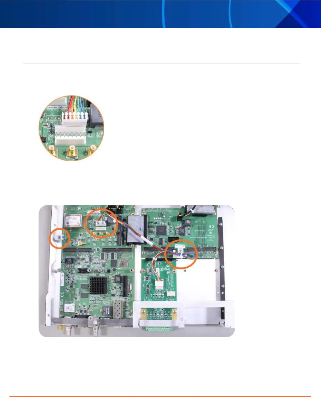
[9]: Alarm Relay Card, Cable Installation
Additional steps for the installation of the Alarm Relay Output card (PN1204-0F).
a.
Connect the supplied cable, part number 8195-0000-5000, to the mainboard connector J19, pins 3 - 8.
Note: Pins 1 and 2 of connector J19 are not used:
Figure 10: J19 Connector, seen from rear of unit.
b.
Using the supplied cable ties, secure the cable, part number 8195-0000-5000, from the option card to the
white nylon cable tie holders fastened to the mainboard (see figurebelow). Use the fastener closest to your
installation location.
Figure 11: Cable routing
SecureSync 2400 Option Card Field Installation Guide