Page 32
Installation and Operation Manual - Osburn 3500
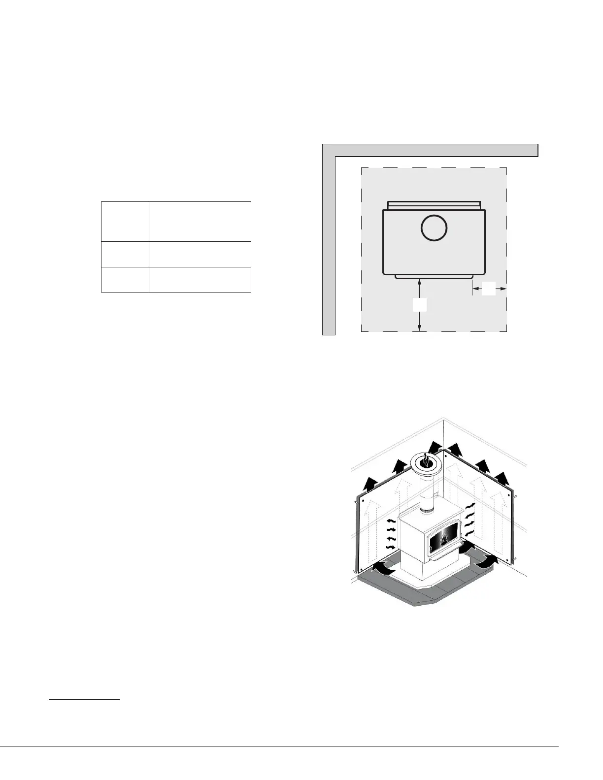
7.3 Floor Protector
If the wood fire is to be installed on top of a combustible floor, it must be guarded by a non-
combustible material as shown on the dotted line area of the above figures. Install a 910 mm
(Width) x 1185 mm (Depth) floor protection of 6 mm of thickness with thermal conductivity of
0.026 m2 K/W per 6 mm thick.
FLOOR
PROTECTION
1
D 300 mm
E 200 mm
2
D
E
Figure 13: Floor Protection
7.4 Reducing Wall and Ceiling Clearances Safely
You may decrease the minimum clearances
to heat-sensitive materials by installing heat
radiation shields between the walls or the ceiling
and the wood fire. These heat radiation shields
must be installed permanently, and must be made
of a heat-resistant or heat-tolerant material.
An air gap must separate the heat shield from
any heat-sensitive surface. Furthermore, the
heat shield shall extend in all directions beyond
the boundaries of the appliance surface by a
distance of not less than 450 mm. Exceptions
may apply. Refer to AS/NZS 2918:2001.
Figure 14: Heat shield
Following the installation of such heat radiation shields, the minimum clearances to heat-sensitive
materials may be reduced by applying the clearances factor in the table below:
1 Bellis board, cement ber sheet or similar. No protection is required if the unit is installed on a non-combustible oor (ex: concrete).
2 The oor protector shall extend not less than 200 mm from each side of any ash removal or fuel loading openings unless the oor protector forms
an abutment with a wall or heat shield at a lesser distance.