EasyManua.ls Logo

OSD Audio SMP500DSP User Manual

OSD Audio SMP500DSP
4 pages
To Next Page IconTo Next Page
Page #1 background imageLoading...
Page #1 background image
~UDIO
SMP500DSP
SUBWOOFER
AMPLIFIER
OWNERS
MANUAL
Description
Thank you for purchasing the SMPS00 DSP by OSD Audio.
This 400W RMS 1 000W Peak DSP amplifier has some
of the most advanced DSP functions available.
Caution:
MAKE
SURE
TO
READ
THIS
INSTRUCTION
MANUAL BEFORE TURNING
THE
POWER ON
OR HOOKING
UP
THIS
POWER AMPLIFIER.
Installing Rack Mount Ears
If you are planning on installing this amplifier into a rack,
continue reading how
to
install the supplied rack ears.
1. Use the supplied three screws
to
attach the supplied
rack ears
to
the SMP500 DSP amp. If required, the feet
on the bottom
of
the amplifier can also be removed at
this time by unscrewing the mounting screws located
in
the center of each foot.
2. Due
to
the weight
of
the amplifier, it is recommended
that rear supports be secured
to
the rear rack rails.
Hardware
to
do this is not supplied with the amplifier
and is specific
to
the type and depth of rack being used.
Amplifier Controls and Setup
Front Panel
% @
+
'""
'
"""
..
...
....
I
1.
Power Switch: Turns the amplifier on or off. Amplifier
must be on for the trigger
or
auto sense modes
to
operate.
2.
16 Character x
2-row
Liquid Crystal Display: Shows
the amplifier's status, menus and settings and works
in
conjunction with the turn and push navigation controls
and the remote control.
3.
Programming Navigation Control: Used
to
scroll
through the display menus, change setting and program
the
DSP
controller.
4. For uploading new firmware or updates.
Back Panel
3
1.
Line Input: For receiving line-level signals. Accepts
either a stereo or
LFE
signal.
2.
Input: For receiving signals. Accepts either a stereo
or
LFE
signal
3.
12V Trigger Input: For triggering the power on/off from
other devides such as processors or receivers that have a
12V trigger output.
6V
minimum required for triggering.
NOTE: Once
in
trigger mode, the amplifier cannot be
turned
on
without a 12V trigger signal.
To
disable the
12V trigger, press and hold the navigation control knob.
The power switch must be
in
the
ON
position. The
trigger mode will be turned off and the amplifier will
power on.
Question and Answer IconNeed help?

Do you have a question about the OSD Audio SMP500DSP and is the answer not in the manual?

OSD Audio SMP500DSP Specifications

General IconGeneral
Channels5
Power Output500W
DSPYes
InputsRCA, Optical, Coaxial, USB
BluetoothYes
Remote ControlYes
Frequency Response20Hz - 20kHz
Dimensions17" x 12" x 3.5"
EQ5-Band Parametric
OutputsSpeaker Outputs
Input Sensitivity200mV
Crossover TypeAdjustable
Protection FeaturesOverload, Short Circuit, Thermal

Summary

Product Description

SMP500DSP Amplifier Overview

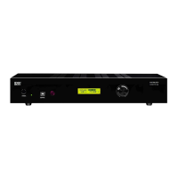
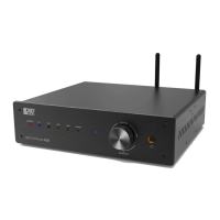
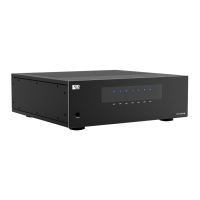
Introduction to the SMP500 DSP amplifier, highlighting its 400W RMS power and advanced DSP functions.

Amplifier Controls and Setup

Front Panel Controls

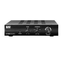
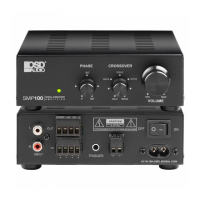
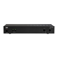
Details the controls located on the front panel of the amplifier for operation and setup.

Back Panel Connections

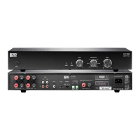
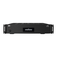
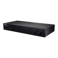
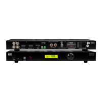
Describes the various input and output ports on the back panel for connecting audio sources and triggers.

Installing Rack Mount Ears

Rack Mount Ear Installation

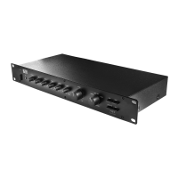
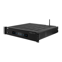
Instructions for attaching the supplied rack ears to the SMP500 DSP amplifier.

Rack Installation Support

Recommendations for securing the amplifier in a rack due to its weight.

Back Panel Features

5-way Binding Posts

Connects your subwoofer here; minimum load impedance is 4 ohms.

Voltage Selector Switch

Allows selection of operating line voltage (110-120V or 220-240V).

Power Cord Receptacle

The connection point for the supplied power cord.

Fuse Holder

Access for the power fuse, with specifications for replacement.

Remote Control

Remote Control Functions

Overview of the remote control buttons and their corresponding functions.

Control Flow Chart - SUB Mode

SUB Mode Settings Flow

Visualizes the navigation path through the amplifier's SUB mode settings.

LCD Display Screens and Functions

Volume Control

Adjusts the system's output volume to match main speakers.

Subsonic Control

Selects the frequency to cut off the high-pass audio signal.

Crossover / Frequency

Selects the frequency for the low-pass audio signal cut-off.

Crossover / Slope

Allows selection of the crossover slope for the low-pass filter.

Preset Mode

Compatible with all brands and types of subwoofers.

Phase Control

Adjusts subwoofer's acoustic phase to match main speakers.

Night Mode

Limits dynamic range for quieter listening.

Auto Off

Automatically turns the amplifier off when not in use.

Mode Select

Allows selection between SUB or LFE modes.

External Trigger

Enables or disables the external trigger function.

Lock Setting

Protects all settings from accidental changes.

Memory Store

Allows selection of memory banks (Mem1, Mem2, Mem3).

Memory Recall

Recalls settings saved using the Memory Store function.

Specifications

Amplifier Specifications

Detailed technical specifications including power output, distortion, and dimensions.

Troubleshooting

No Sound from Subwoofer

Diagnoses and tests for common causes of no sound output from the subwoofer.

Sound from One Subwoofer Only

Troubleshooting steps for when only one subwoofer is producing sound.

Warranty Information

OSD AUDIO Limited Warranty

Details the 2-year limited warranty, claim procedures, and exclusions.

Related product manuals