OWNERS
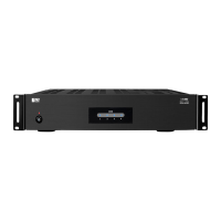
SMPS500DSP
MANUAL
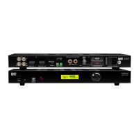
4.
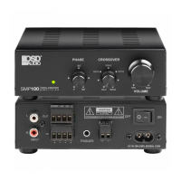
5-way
Binding
Posts:
Connect
your
subwoofer
here.
Minimum
impedance
of
the
load
is
4
ohms.
Multiple
subwoofers
can
be
connected
if
the
combined
load
impedance
is
4
ohms
or
greater.
5.
Voltage
Selector
Switch:
The
amplifier
can
be
used
on
110~120V
(60HZ)
or
220~240V
(50HZ)
line
voltage.
To
change
the
operating
line
voltage,
turn
the
power
off
using
the
power
button
and
unplug
the
power
cord.
Remove
the
plastic
cover
screws
and
the
plastic
cover
over
the
voltage
selector
located
on
the
rear
of
the
amp.
Set
the
switch
to
the
correct
position
for
the
line
voltage
in
your
country.
Replace
the
plastic
cover
and
screws
over
the
voltage
selector
switch.
NOTE:
If
required,
remove
the
IEC
line
cord
and
replace
with
an
IEC
AC
cable
that
matches
the
AC
wall
socket,
this
should
be
a
10A
rated
cable.
When
the
voltage
selector
switch
is
changed,
the
fuse
must
also
be
changed
to
continue
to
provide
protection
to
the
amplifier.
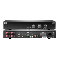
6.
Power
Cord
Receptacle:
The
supplied
power
cord
needs
to
be
connected
to
this
receptacle
in
order
for
the
amplifier
to
work
properly.
7.
Fuse
Holder:
This
is
the
power
fuse
access.
WARNING!
In
the
event
the
fuse
must
be
replaced,
the
replacement
fuse
must
match
exactly
the
original
fuse
value
or
damage
to
the
amplifier
may
result.
Use
a
6.3A120V
or
3.15A
240V
fuse.
CAUTION!
Before
replacing
the
fuse,
disconnect
the
power
cord
from
the
power
receptacle.
10MM
20MM
(#2.0)
(40.5)
5.2MM
tao
4/-0.2)
L____
REMOVE
FUSE
HOLDER
HERE
NOTE:
A
spare
fuse
is
also
located
in
this
holder
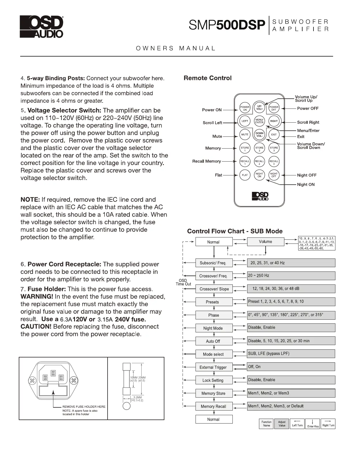
Remote
Control
Power
ON
——
Scroll
Left
Mute
Memory
Recall
Memory
Flat
—=
OSD
___
Volume
Up/
.
Scroll
Up
Power
OFF
Scroll
Right
Menu/Enter
Exit
Volume
Down/
Scroll
Down
—
Night
OFF
|
Night
ON
EEAUDIO
Control
Flow
Chart
-
SUB
Mode
>|
|
|
Normal
i
Volume
he
10,9,8,7,6,5,
4.3.24,
0,-1,-2,-3,-5,-6,-7,-9,-11,-13,
—*)-45,-17,-19,-23,-27,-31,-35,
J
Subsonic/
Freq.
|
20, 25,
31,
or
40
Hz
y
OSD
Time
Out
I
Crossover!
Freq.
|<
[20
~
250
Hz
Y
i
Crossover!
Slope
|
12,
18,
24, 30, 36,
or
48
dB
Y
_
Presets
[Preset
1,2,
3,
4,5,
6,7,
8,
9,
10
|
i
eee
—
io",
45°,
90°,
135°, 180°,
225°, 270°,
or
315°
|
y
[Disable,
Enable
—_
|
i<—
Night
Mode
|
y
|
i+—
Auto
Off
y
|
i~—
Mode
select
|
1
|
|
External
Trigger
|
Off,
On
y
—
[Disable,
5,
10,
15,
20,
25,
or
30
min
——
|
SUB,
LFE
(bypass
LPF)
|
|
Lock
Setting
y
——
|
Disable,
Enable
|
\_—§
Memory
Store
|
Mem1,
Mem2,
or
Mem3
1
|
<=
Memory
Recall
<
|
Mem1,
Mem2,
Mem3,
or
Default
y
Normal
Function
Name
Adjust
Value
—
Left
Turn
—
Right
Turn
Enter
Key