PC-30 Filter control unit operating manual Page: 10
regulation only works correctly with precisely balanced
sensors, this balance should only be carried out by a trained
service technician.
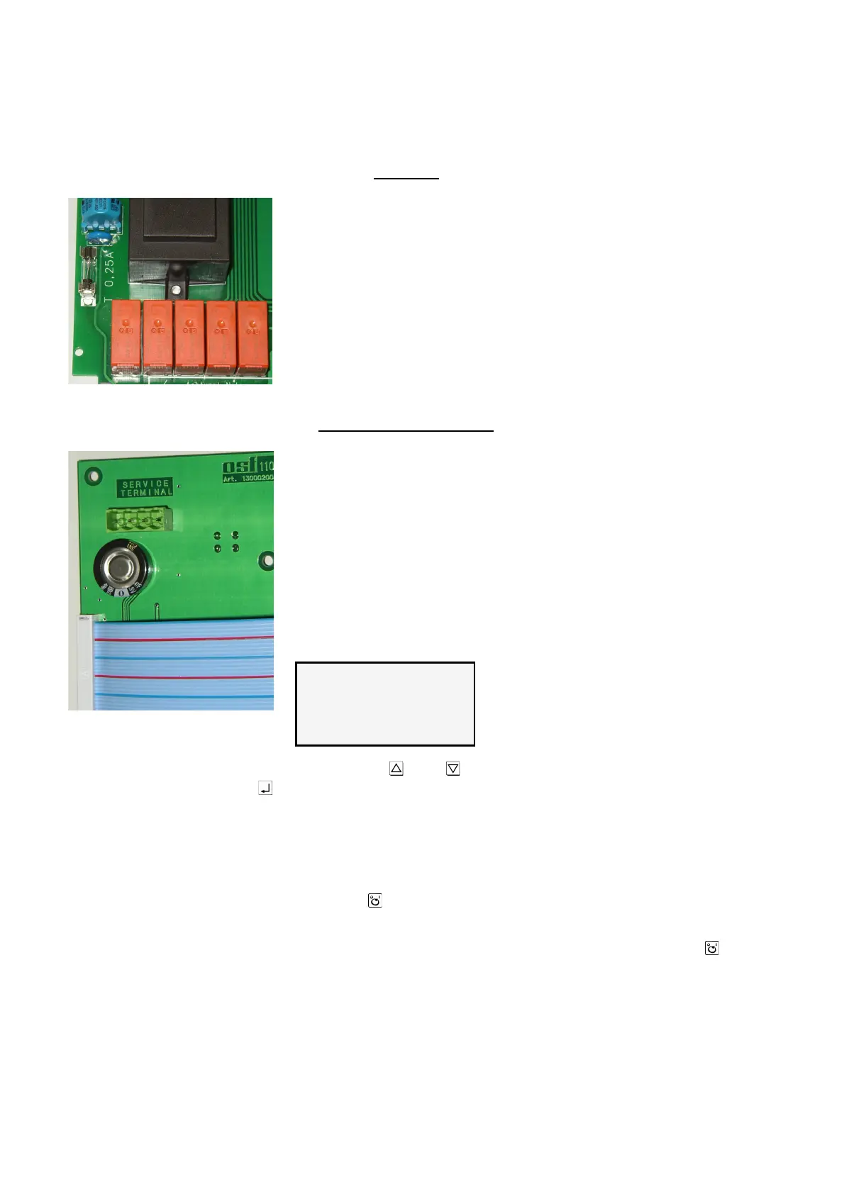
Fuses
The electronic control system is protected by a 0.25A fine-wire
fuse on the PCB in the inside of the device. The short-circuit
protection for the filter pump must be provided by a backup
fuse of maximum 16A on site.
Service terminal
An osf service terminal (Art. No. 3010000900) can be
connected to this control system for optimum control system
settings for a wide range of swimming pool equipment and for
assisting in initial startup and fault diagnosis. The socket for
this is located on the PCB inside the device. Before opening
the housing and plugging in the service terminal, you
must ensure that the control system has been isolated
from the mains! Once the control system has been switched
on, the service terminal display shows the first 4 lines of the
diagnosis text, e.g.:
Further lines can be called up using the and keys. Values in the top line can be
changed by pressing the key if necessary.
Filter unit operating mode
This line displays the current filter unit operating mode.
The following displays are possible:
Control system off Use the key to switch the control system off.
Filter unit off The filter unit is switched off.
Filter operation The filter unit is switched on using the timer or the key
on the front cover.
Run-on time The filter pump continues running when the heater is
switched off.
Forced switching The filter pump is either switched on by the
EUROTRONIK-10 backflushing controller or the NR-12-
TRS-2 level regulation system.
Priority circuit Outside the set filter times, the filter pump is switched on