12
Check Socket Electrodes
Use the check socket electrodes during the check socket process (Fig. ). This allows the position of the electrode
to be moved during the test fitting stage.
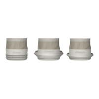
Compact Electrodes
During fabrication of the silicon socket make a recess at the correct position for the compact electrode. Use the
supplied dummies. The top of the compact electrode must be above the inner surface of the silicon socket.
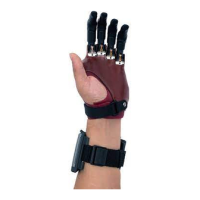
FSRs
When using FSRs, the FSR (Fig. ) should be positioned between the silicone socket and the inner lamination.
A flat surface must be created on the inner lamination to ensure the FSR is not bent when assembled.
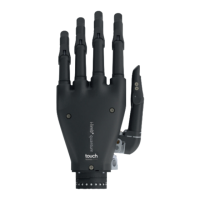
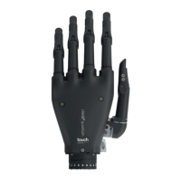
. FINISHING OPTIONS
Two finishing options are possible, with knuckle fairings either incorporate or exposed within the lamination. If
using incorporated fairings, the supplied modified fairings and knuckle dummy must be used during lamination.
(Fig. , )
. ASSEMBLY
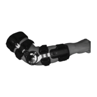
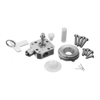
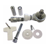
Thumb Rotator Assembly – Setting and Assembly
Assemble the thumb rotator in the correct order of parts (Fig. ). To increase the force required to rotate the
thumb, remove the nut cap and use the mm spanner to tighten the M locking nut. The grub screw will need to
be loosened to tighten the nut.
NOTE: make sure the clutch plate is not contaminated as this will affect performance.
Hand tighten with fingers and then turn a further ° to ° using the mm spanner to set thumb friction to
patient preferences (Fig. ). The wire will pass through the center of the spigot.
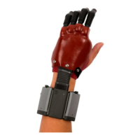
Attaching the Thumb
– Remove the base cap on the thumb rotator assembly by removing the two Mx mm screws (Fig. ).
– Remove the knuckle cover from the thumb assembly by removing the two Mx mm screw. (Fig. ).
– Remove the knuckle assembly from the thumb by removing the M grub screw (Fig. ).
– Screw the knuckle onto the thumb rotator assembly using three Mx mm screws (Fig. ).
– Using a torque driver set to Nm, re-attach the thumb to the single knuckle assembly (Fig. ).
– Slide the knuckle fairing over the back of the thumb and attach using two Mx mm screws (Fig. ).
– Thumb digit wire should be fed through the central hole in the spigot exiting at the base cap end.
– Re-attach the base cap, using the screws previously removed.
– Add connector onto each of the thumb digit wires. Make sure digit wire ‘tooth’ is fully secured into the
connector (Fig. ).
– After diagnostic fitting, remove the thumb wire connector to enable fabrication of the definitive prosthesis.
– To remove connector from thumb wire:
– Place small flat screwdriver under tab of connector and lift up (Fig. ).
– Gently pull on digit wire to release from connector.
NOTE: use a new connector each time.
. WRISTBAND WIRING CONNECTIONS
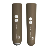
– Remove the bellows cover by gently pulling it over the socket end of the bellows assembly.
– Remove bellows from wristband (Fig. ).
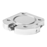
– Remove screws to release top collar and PCB from bellows assembly (Fig. ).
Connecting the Digits to the Wristband
(Fig. )
– Slide the digit wires through the aperture at the front of the bellows assembly.
– Insert the digit wire connectors into the bellows PCB. A click should be felt when fully inserted (Fig. ).
 Loading...