58
External Communications
Table 4 is a summary of the SDI-12 user commands supported by the multiprobe. For
more details on correct use, consult the SDI-12 V1.2 specification.
B.2 Connection to an External Device
The Series 5 Multiprobe can communicate with an external device using an RS232,
RS485, or SDI-12 interface. The RS232 interface is always available. The Series 5
Multiprobe must be programmed for communication via an RS485 or SDI-12 interface.
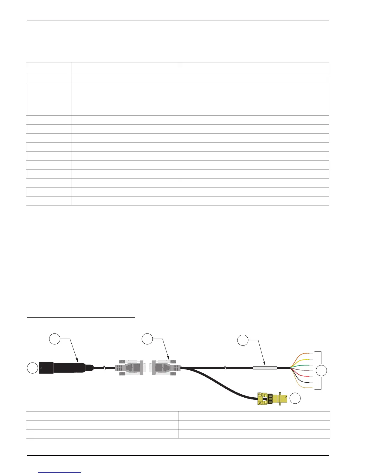
Two cables are available for external communication: a 6-pin marine to DB-9 cable
(Cat. No. 015xxx), and a DB-9 to external device cable (Cat. No. 013510) for SDI-12 or
RS485 interfaces (Figure 20). Wiring diagrams for these cables are shown in Figure 22
and Figure 23. Wiring for the 6-pin Sonde connector is shown in Figure 21. Wiring to the
external device is detailed in Table 5.
Figure 20 Communication Cables for the DS5, DS5X, and MS5 Water Quality Sondes
Table 4 SDI-12 Commands
Command
1
Response Description
a! a<crlf> Address Acknowledge
aI!
aXXHydrolabYYYYYYZZZZserialnumber
<crlf>
Identify
XX: SDI–12 Support Version
YYYYYY: Instrument ID
ZZZZ: Software Version
aAb! b<crlf> Change address from a to b
aM! adddn<crlf> Measure n values in ddd seconds
aDx! aSvalueSvalue...<crlf> Report Data
aRx! aSvalueSvalue...<crlf> Report Continuous Data
aC! adddnn<crlf> Concurrent Measure: nn values in ddd seconds
aXC! aXC<crlf> Initiate a cleaning cycle in units equipped with a wiper
aX1! aX1<crlf> Enable Continuous Mode
aX0! aX0<crlf> Disable Continuous Mode
aXSS1! aXSS1<crlf> Circulator On
aXSS0! aXSS0<crlf> Circulator Off
1
The 'a' used in the SDI-12 commands is the SDI-12 address. The Transmitter's factory default SDI-12 address is '0'.
1. Cable, 6-pin marine to DB-9 (Cat. No. 015XXX) 4. Label, wire connections
2. Connection to DS5, DS5X or MS5 5. Connections to external device
3. Cable for SDI-12/RS485 (Cat. No. 013510) 6. Connection to power
13
4
5
6
2