J2
J1 J4
J3
OPEN:0.3to12ms
CLOSE:5to250ms
1
2
P1
Pulsewidthadjust
(MM:Pulsewidthadjustcircuit)
1:1waveshape
circuit
MM
DCpowertopulsegenerator
DCpowertothelogics
2,3,4
11,1
FLOWIN
POWER
5,6
7, 8
9,10
OUT1
OUT2
OUT3
TP2
TP1
1
2
OPEN:One-shot
CLOSE:Uppercutoff
Generatorselect
circuit
Powersupply
circuit
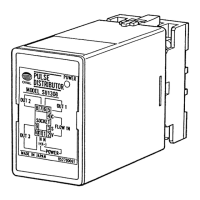
4. WIRING
(1) Separate eld wiring from other power lines
or power circuits to minimize the possibility
of inductive interference.
(2) Terminal arrangement is shown in Fig. 4.1.
(3) M3.5 ×7 screws are used for terminals.
Ensure good electrical connections.
(4) Upon completion of wiring connections,
install the distributor body into the socket.
Then engage the locking levers on the
socket assembly with the distributor body.
(5) For incoming signal cables from the owme-
ter or other signal sources, cables recom-
mended for the instrument of interest must
be used. Transmission length also depends
on the specication of that instrument.
For other signal cables, electrostati-
c a l l y - shielded, polyethylene-insulated,
vinyl-sheathed control cables (CEVS 1.25
to 2.00mm
2
, 2- or 3-conductor), or equiv-
alent, must be used. With a conductor area
2 mm
2
, the maximum transmission length is
one kilometer.
CAUTION
Make electrical connections upon conrmation of validity of owmeter (pulse gen-
erator) and receiving instrument combination by their model No., serial No., etc.
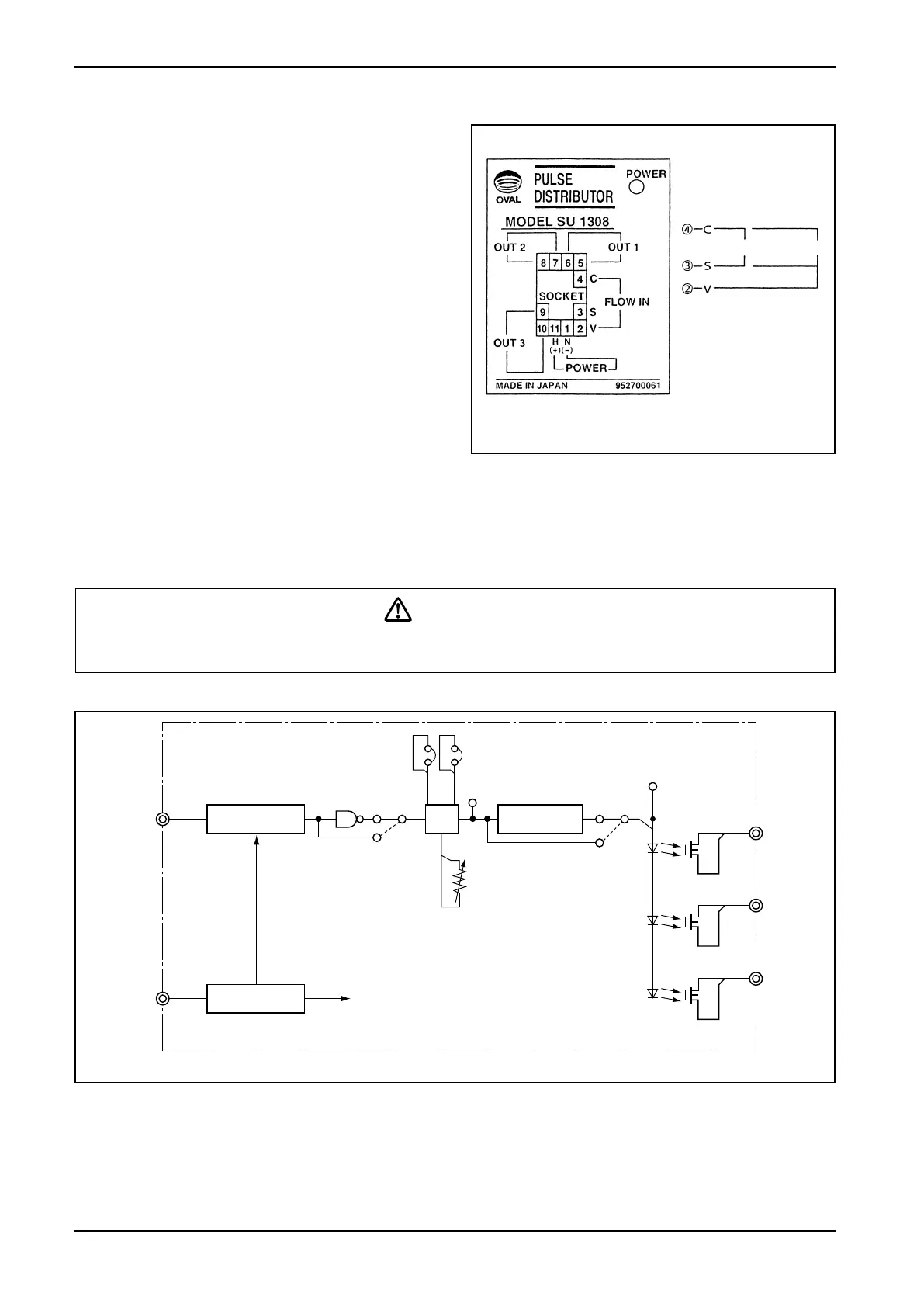
● Description of Individual Circuits (by block)
●
Pulse generator select circuit
………Selects the acceptable signal type of pulse generator and shapes the waveform.
●
Power supply circuit……………Furnishes power of required voltage to individual circuits.
●
Pulse width adjust circuit ……Selects the “ON” duration of output pulse signals OUT 1, 2, and 3.
●
1:1 waveshaping circuit………Adjusts the ON/OFF ratio of output signals OUT 1, 2, and 3 to 1:1.
5. OVERALL BLOCK DIAGRAM
Fig. 5.1
Fig. 4.1 Terminal Identication
Wiring Connections
● FLOW IN terminals
2-wire sig. 3-wire sig.
● OUT1, OUT2, OUT3
Polarity observation
is not required.