Jumper Input pulse mode (pulse generator)
J1 Voltage pulse (Code 3 only): 2 Others: 1
● Output Setting:
Establish output mode.
Jumper
Output mode
One-shot output Upper cuto output
Duty sync with input
1:1 output
J2 OPEN CLOSE OPEN
J4 2 2 1
J5 OPEN CLOSE
● Output Pulse Width Setting and Adjustment:
Jumper Pulse width adjust range (adjustable with P1) Location
J3 OPEN:0.3 to 12ms CLOSE:5.0 to 250ms TP1and 0VB
(If output mode is “Duty sync with Input 1:1
”,
it adjustment is correct at 1 ms. )
8. INDIVIDUAL JUMPER SETTING
● Input Setting: Establish input pulse mode.
Establish parameters such as “ON” width or cuto width of output pulse signal.
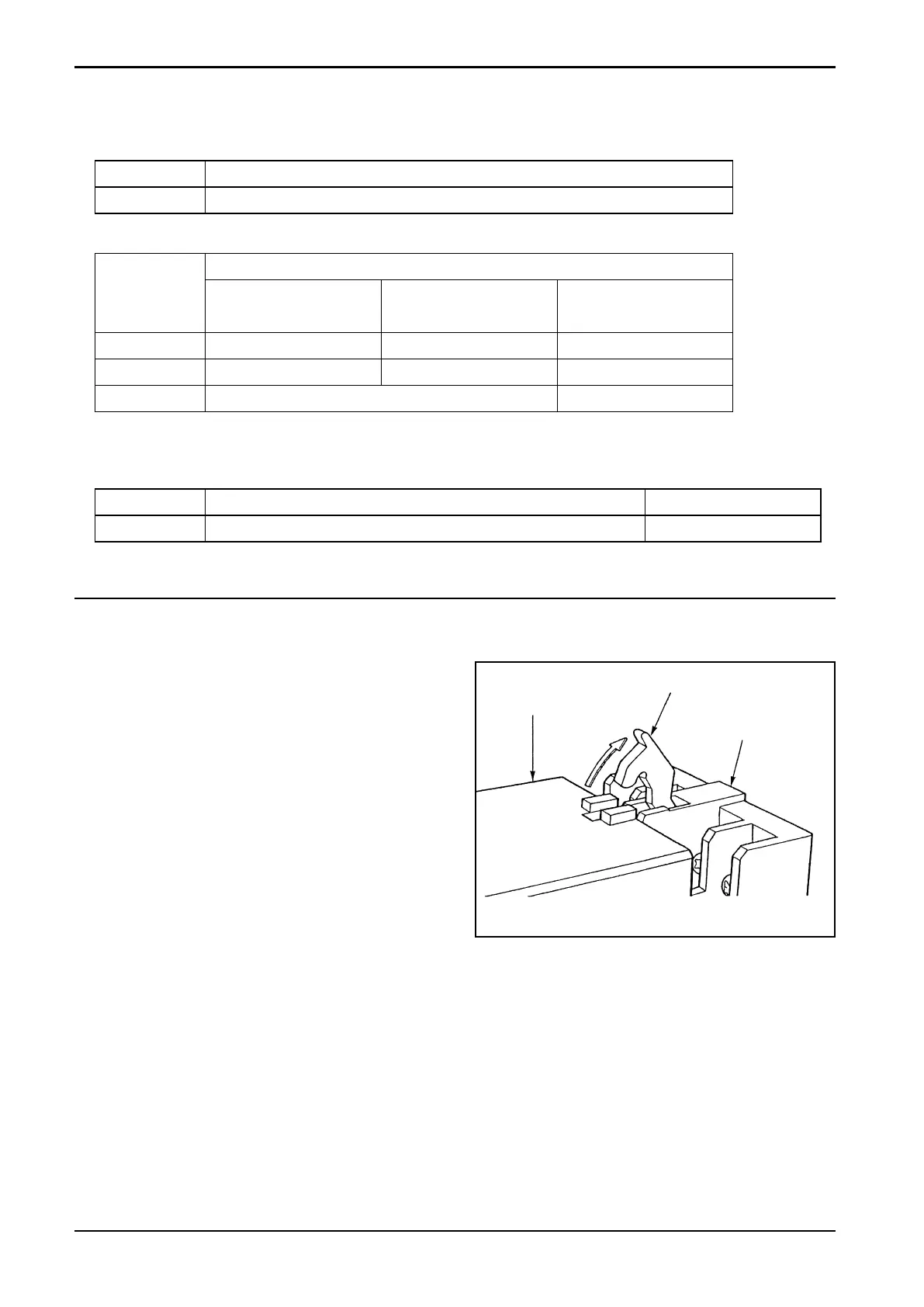
8.1 Enclosure Removal
(1) Unlatch the locks of socket assembly,
separate the distributor body and remove
the enclosure (see Fig. 8.1).
(2) Referring to the pictorial drawing showing
component locations (Fig. 7.1) on page 5,
make adjustments required.
Enclosure
Lock Lever
Surface Mount
Socket
Fig. 8.1