Cancellation of limitation or blocking
If the control range is limi-
ted or blocked with the
clips, the handgrip cannot
be removed as shown on
photo 1 or 12. In this case
the following method should
be used:
lllustr.16: Blocked tempe-
rature setting: Insert tool
(item no. 198 91 00) on top
of the handgrip so that one
bridge is in the groove immediately before and one brid-
ge in the groove immediately after the indicator mark. Push
tool in direction of arrow to loosen the clips. Remove tool.
Limited control range: Turn the handgrip to minimum and
maximum value respectively of set control range. Place tool
on top of the handgrip so that one bridge is in the groove
immediately before and one bridge in the groove imme-
diately after the indicator mark. Push tool in the direction
of arrow to loosen clips. Remove tool.
The handgrip can now be removed as shown on photo 1.
Remove clips and reposition.
16
Blocking the temperature setting
To prevent unauthorised tampering, any temperature
setting of the thermostat can be locked. Example: Blocking
temperature setting to figure “2”. (equals approx. 16 °C,
e.g. for hallways and bedrooms). To do so, first remove
handgrip as described beside photo 1. Then turn sensor
casing until the calibration mark (bore or white stroke) is
i
n line with the indicator mark (as described beside pho-
t
o 2).
Photo 8: Replace handgrip
loosely so that figure “3” is
in line with the indicator
mark.
8
Photo 9: Turn handgrip to fi-
gure “2” while pressing it
gently. Remove handgrip.
(The calibration on the sen-
sor casing is now turned to
the right.)
9
Photo 10: The two clips on
the inner side of the hand-
grip are to be removed as
described beside photo 3
and to be placed in the
grooves immediately befo-
re and after figure “2”. (The
groove directly opposite fi-
gure “2” thus remains free.)
10
Photo 11: The handgrip
now is to be replaced so
that figure “2” is in line with
the indicator mark. The set-
ting is now blocked in po-
sition “2” (approx. 16 °C).
Push down handgrip with
hand firmly to secure.
11
Recalibration
The thermostat is adjusted at works to 20 °C = figure “3”.
Should this adjustment be altered, you can recalibrate as
follows:
12
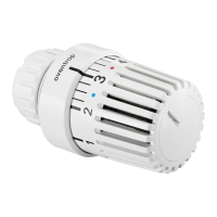
Photo 12: To remove the
handgrip either the tool
(item no. 198 91 00) or a
suitable pin, e.g. the push
button of a pen, should be
inserted in the hole on the
lower side of the thermost-
at. By turning the handgrip
to the right into shut-off
posi tion, it is easily remo-
ved.
13
Photo 13: Remove handgrip.
Turn sensor casing to the
right until it is fully screwed
into the body of the ther-
mostat, then turn to the
left again until the calibra-
tion mark (bore or white
s
troke) is in line with the in-
d
icator mark.
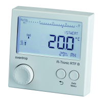
14
Photo 14: If the sensor ca-
sing is for some reason
unscrewed completely from
the body of the thermostat,
please note that when re-
placing the element, be-
cause of the double start
thread, the correct start
thread is used. After reca-
libration, the distance bet-
ween the body and the
sensor casing has to be
approx. 6 mm.
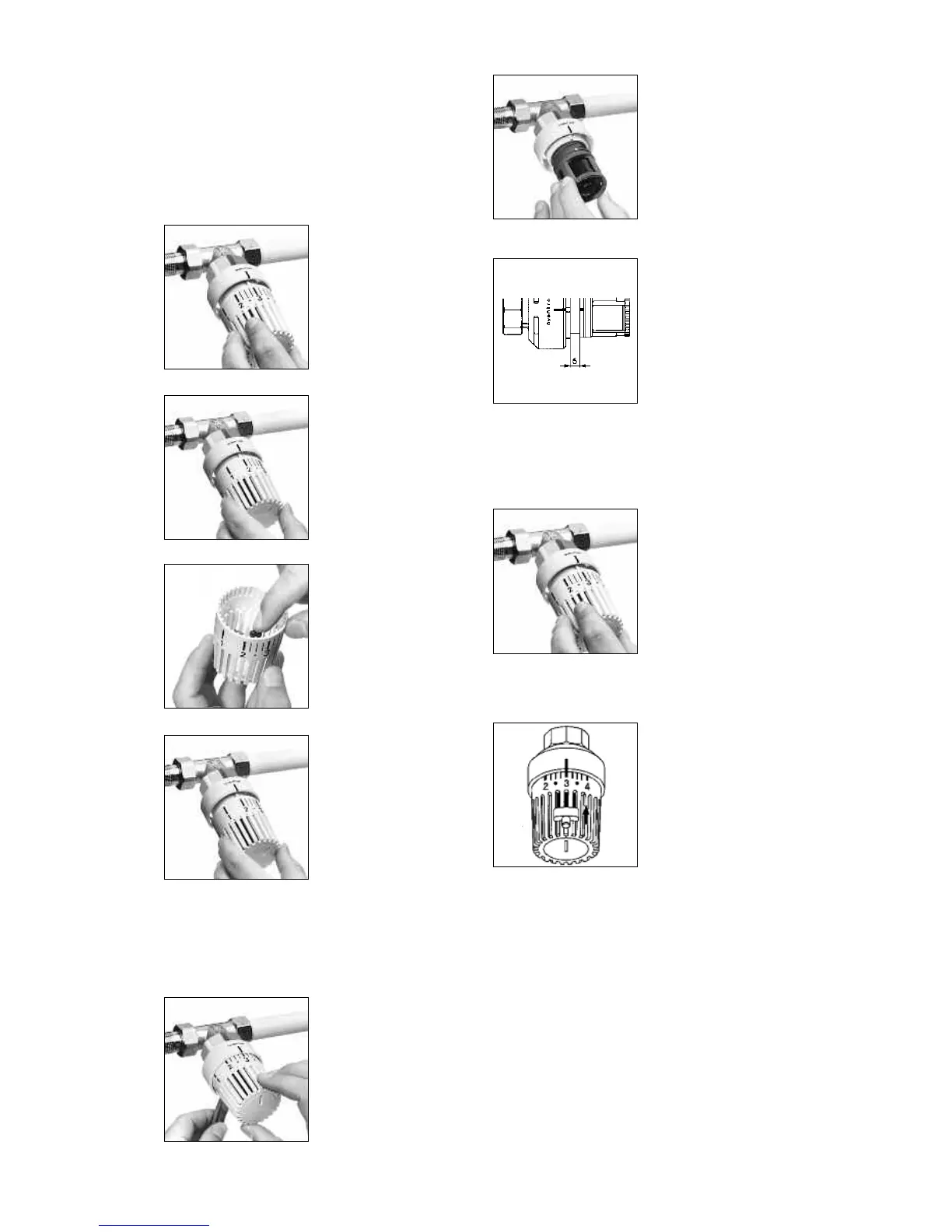
15
Photo 15: Replace handgrip
so that figure “3” on the
handgrip is in line with the
indicator mark. Push down
firmly with hand to secure.
7
 Loading...