Do you have a question about the OWC data doubler and is the answer not in the manual?
Details compatibility requirements for Mac mini models and storage drives.
Lists all items included in the OWC Data Doubler kit.
Provides information on potential variations and product specification updates.
Step-by-step instructions for carefully disassembling the Mac mini.
Detailed guide on mounting the Data Doubler and a drive into the Mac mini.
Guides users through common issues and their resolutions.
Advice on protecting data and maintaining multiple backups.
Provides contact information for OWC technical assistance.
Essential safety guidelines for handling static-sensitive devices and preventing damage.
Details FCC regulations and compliance for the device.
Advises on environmental conditions, electrical safety, and device care.
The OWC Data Doubler is an internal drive upgrade kit designed specifically for the Apple Mac mini (2010 model, identifier Macmini4,1) that originally came with an optical drive. Its primary function is to allow users to install a second 2.5-inch SATA drive (either a hard disk drive or a solid-state drive) into their Mac mini, replacing the optical drive. This enables users to expand their storage capacity or improve performance by adding an SSD for the operating system and frequently used applications, while retaining a traditional hard drive for mass storage.
The installation process involves disassembling the Mac mini to access its internal components and then integrating the Data Doubler with the new drive into the optical drive bay. The kit includes the Data Doubler frame, which securely holds the new 2.5-inch SATA drive, along with necessary mounting screws. To facilitate the installation, OWC provides a five-piece toolkit and a specialized Mac mini logic board removal tool. The manual emphasizes the importance of proper screw organization during disassembly, suggesting the use of an ice cube tray or similar device to keep track of the various screws, as they differ in size and type.
The first step in the installation involves preparing the Mac mini by placing it upside down on a soft surface to prevent scratches. The bottom cover is then rotated counterclockwise to unlock and remove it, revealing the internal components. Users are guided to remove the two memory modules, following the instructions printed inside the Mac mini. Subsequently, three Torx T6 screws securing the fan are removed, noting that two are shorter and one is a longer standoff screw. The fan cable is then disconnected from the logic board by lifting the connector straight up, with the plastic pry tool assisting in this delicate step.
Further disassembly requires removing a short T6 screw at the bottom of the black plastic cowling. The cowling itself is then carefully lifted and rotated clockwise to remove it, ensuring it doesn't catch on other hardware. Five Torx T8 screws are removed from the logic board, with a note that some are 2mm hex screws but can be managed with a T8 screwdriver, cautioning against excessive force. The antenna plate is gently lifted and moved to reveal the antenna cable connected to the wireless card, which is then disconnected by lifting it straight up, again emphasizing its fragility.
The hard drive flex cable and the optical drive flex cable are disconnected from the logic board using the nylon pry tool. A T6 screw at the bottom left of the logic board is removed. The logic board removal tool is then inserted into two specific holes at the bottom of the logic board to aid in its extraction. Gently pushing down on the tool and pulling back causes the black plastic I/O wall to separate slightly from the aluminum housing. Four additional cables are disconnected from the logic board by lifting their connectors straight up. The power supply cable is then disconnected by wiggling the connector out.
With all cables disconnected, the logic board assembly is carefully slid out of the housing, keeping it level to avoid catching components, especially the memory bracket. The power supply is removed by first taking out a T6 screw and then pulling the power supply straight out, possibly with a slight rotation. The hard drive is then slid out of the housing. A T6 screw securing the optical drive carrier to the housing is removed, and the entire optical drive assembly (including the optical drive and carrier) is removed.
The optical drive flex cable's tape is peeled back from the optical drive, as this tape will be reused. The optical drive flex cable is disconnected from the optical drive, noting that one end is trapped between the optical drive and the carrier, so it should be slid up and out of the way. Four T8 screws securing the optical drive to its carrier are removed; these screws are held in place by rubber grommets and will remain in the carrier. Finally, the optical drive is removed from its carrier, and the optical drive flex cable can also be removed.
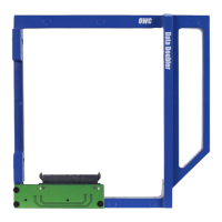
Once the Mac mini is disassembled, the Data Doubler installation begins. The Data Doubler, which has a clear plastic shield on its bottom that should not be removed, is taken from its packaging. A 2.5-inch SATA drive is then installed into the Data Doubler by sliding its SATA connector into the black SATA connector on the Data Doubler's green circuit board. Two Phillips screws are then inserted through the Data Doubler's screw holes into the drive to secure it.
The Data Doubler, with the new drive installed, is then inserted into the optical drive carrier. The optical drive flex cable is connected to the Data Doubler, ensuring there is enough space between the carrier and the drive. Four T8 screws are installed to secure the Data Doubler to the optical drive carrier. The tape previously removed from the optical drive thermal sensor cable is then carefully removed from the optical drive. The optical drive thermal sensor cable is detached from the optical drive using the nylon pry tool, noting its adhesive and fragility. The position of this cable on the optical drive is important to remember.
The optical drive thermal sensor cable is then placed on the new drive in the Data Doubler, aligning it as closely as possible to its original position on the optical drive, ensuring the bend in the lower end of the cable crosses over the optical drive carrier. The original tape is used to secure the optical drive thermal sensor cable to the drive in the Data Doubler. Another piece of tape, also from the original optical drive, is used to secure the optical drive flex cable.
The optical drive carrier and Data Doubler assembly are then slid back into the aluminum housing. The T6 screw that secures the optical drive carrier to the housing is reinstalled. The original hard drive is slid back into the housing, ensuring its pegs fit into the corresponding grommets. The power supply is slid back into the housing, aligning its two pins with the notches inside the housing. The power cord socket is rotated back to its original position, with a suggestion to plug in the power cord (not into an outlet) to help straighten the socket if needed. The metal retention clip is slid back into its groove to hold the power cord socket.
The T6 screw that fastens the power supply to the housing is reinstalled. The logic board is carefully slid most of the way back into the housing, ensuring all clips and gaskets enter correctly and that it clears the hard drive. The power supply cable is reconnected, and then the logic board is slid the rest of the way in. The six remaining cables are reconnected to the logic board by gently pushing down on them until they snap into place. The T6 screw at the bottom left of the logic board is reinstalled.
The antenna cable is reconnected to the logic board. The antenna plate is moved back into place, ensuring it fits into the notch in the housing and aligns with the screw holes. The five Torx T8 screws (including the 2mm hex screws) are reinstalled to secure the antenna plate. The black plastic cowling is reinstalled by rotating it slightly counterclockwise. The short T6 screw at the bottom of the cowling is reinstalled. The fan cable is reconnected to the logic board.
Finally, the fan is lined up, and the three T6 screws (two shorter, one longer standoff) are reinstalled. The two memory modules are reinstalled according to the instructions. The bottom cover is installed and rotated clockwise until it locks into place.
Maintenance features primarily revolve around troubleshooting. If the Mac mini fails to turn on or experiences issues like no sound or wireless connectivity, users are advised to review the assembly instructions to check for incorrectly connected or damaged components. If the drive in the Data Doubler is not recognized on a Mac, users should check the Finder sidebar and Disk Utility. For Windows users, Disk Management should be checked. If the drive is seen but not accessible, it may need to be formatted, with OWC providing resources for this.
The manual strongly emphasizes data backup as a crucial maintenance practice. Users are advised to maintain two copies of their data: one on the Data Doubler drive and another on their primary internal drive or an external storage medium. This precaution is highlighted to prevent data loss or corruption, for which OWC disclaims liability.
General use precautions include avoiding extreme temperatures, unplugging the computer during lightning risks or extended disuse to prevent electrical shock, and keeping the device away from other electrical appliances or magnetic interference sources that could affect its operation. Users are also cautioned against placing heavy objects on the device, exposing it to excessive dust, or using it near water or in damp conditions to prevent damage, electrical shock, or fire. Disassembly or modification of the device by the user is discouraged to avoid risks and maintain warranty.
The manual also includes FCC statements regarding compliance and potential interference, advising users on measures to correct interference if it occurs. Health and safety precautions reiterate the importance of anti-static measures during installation to prevent damage to static-sensitive devices. It warns against disassembling or modifying the device, inserting metallic objects, or exposing it to liquids to avoid electrical shock, fire, or injury.
| Installation Type | Internal |
|---|---|
| Interface | SATA |
| Compatibility | 9.5 mm or thicker SATA optical drive bay |
| Drive Type Supported | 2.5-inch SATA HDD/SSD |
| Included Accessories | Mounting screws |