00010605 B 5
2 SYSTEM CONSTRUCTION AND FUNCTION
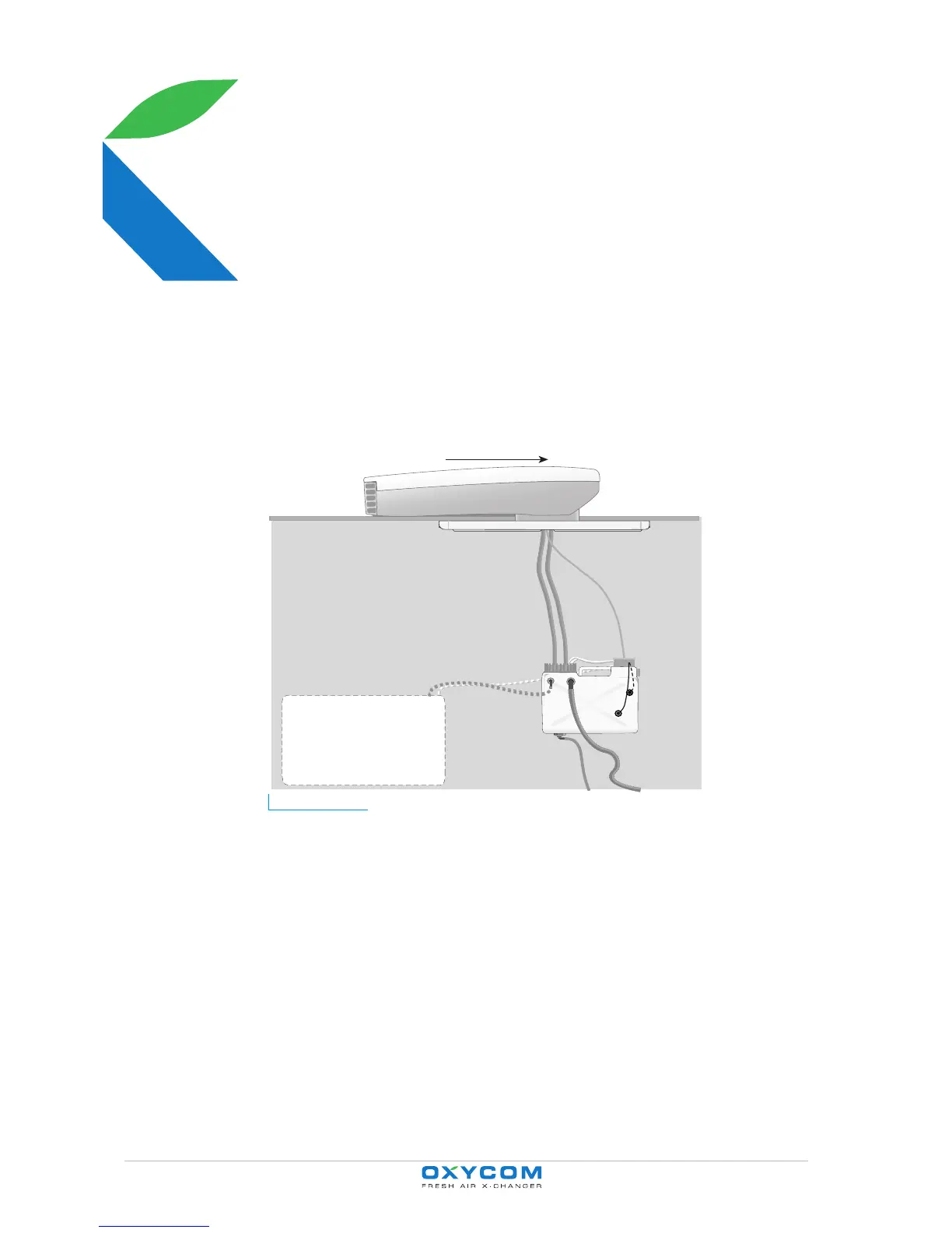
2.1 Construction of the CABIN 400 ventilation and
cooling system
Figure 2.1 Schematic diagram showing the installed CABIN 400 system. The arrow indicates the
direction of vehicle movement.
• The roof unit (1): contains the OXYCELL (heat exchanger) and the fan.
• Inside the vehicle:
- The OXYZONE (2) allows adjustment of the horizontal and vertical air streams.
The operator panel is fitted to the OXYZONE.
- The water reservoir (3) for the water feed to and return from the roof unit
(OXYCELL), complete with screw-on cap (4) and connection box (5).
- Water feed hose (6), water return hose (7), reservoir drain hose (14), water
reservoir overflow (9).
- There are two pumps in the water reservoir. The feed pump delivers water to the
sprinkler in the OXYCELL (heat exchanger) in the roof unit. The return pump
returns excess water to the water reservoir.
1
2
3
4
5
67
8
10
13
11
9
12
14