3/8” LP
33
Fitting the guide bar and chain
1. Loosen the chain cover lock and remove the chain sprocket
cover.
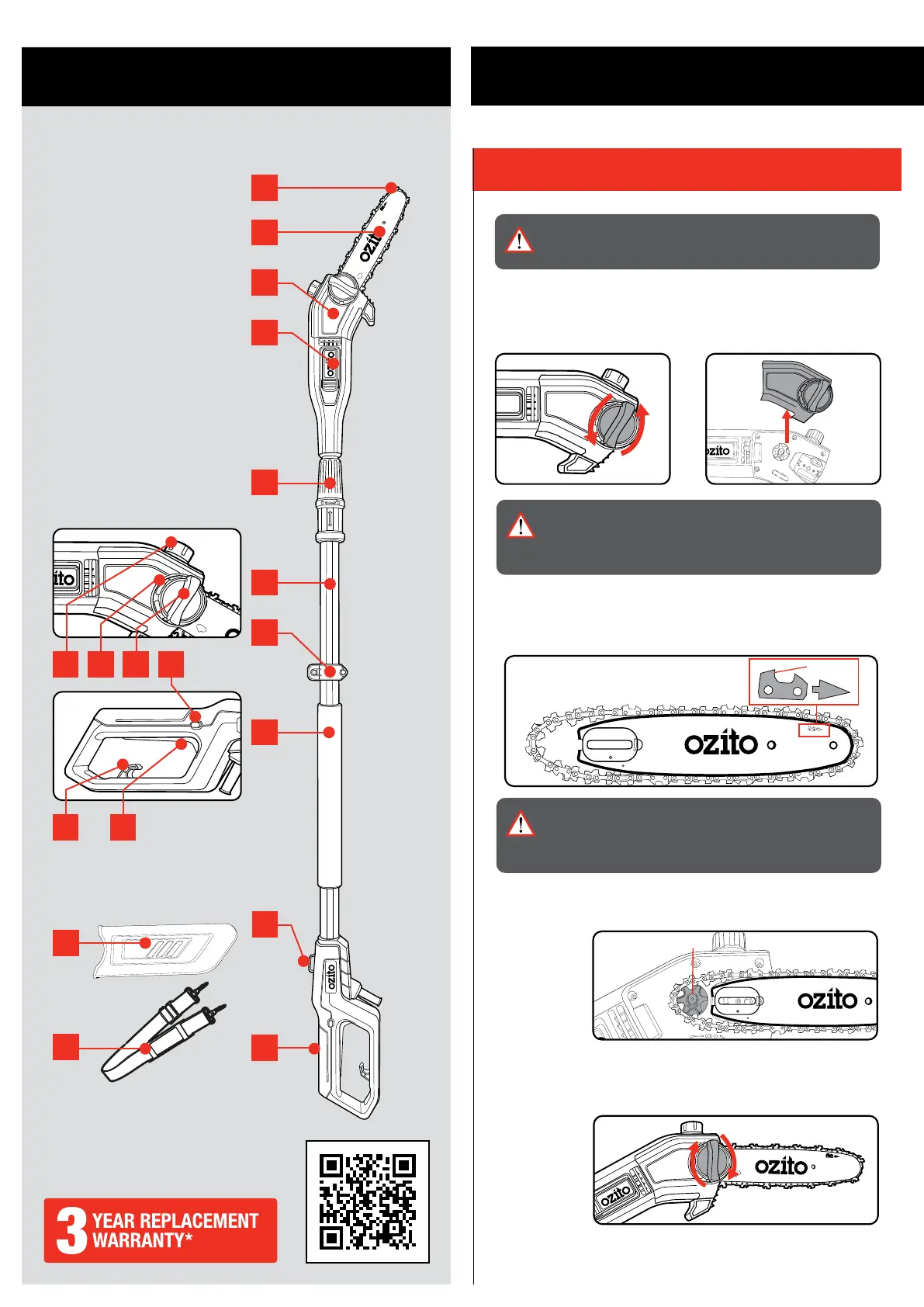
1. Chain
2. Guide bar
3. Chain sprocket cover
4. Motor housing
5. Telescopic tube collar
6. Main tube
7. Shoulder strap retainer
8. Soft grip handle
9. Rear handle
10. Oil tank cap
11. Chain tension dial
12. Chain cover lock
13. Safety switch
14. Extension cord retainer
15. Trigger switch
16. Guide bar cover
17. Shoulder strap
TELESCOPIC POLE PRUNER
ACCESSORIES
KNOW YOUR PRODUCT
1. CHAIN & BAR ASSEMBLY
SETUP & PREPARATION
1
2
3
4
8
9
5
10
11
12
6
7
WARNING! ENSURE THE MACHINE IS TURNED OFF AND
DISCONNECTED FROM THE POWER SUPPLY BEFORE
PERFORMING ANY OF THE FOLLOWING OPERATIONS.
ONLINE MANUAL
Scan this QR Code with your mobile
device to take you to the online manual.
13
14 15
WARNING! THE CHAIN HAS SHARP EDGES, FOR YOUR
OWN SAFETY, PLEASE USE WORK GLOVES. NEVER
TOUCH THE CHAIN OR SERVICE THE UNIT WITH THE
POWER SUPPLY CONNECTED.
2. Place the chain in the groove of the guide bar as shown.
Refer to the image printed on the guide bar that indicates the
direction that the chain should face.
WARNING! IF THE CHAIN IS INSTALLED BACKWARDS
(CHAIN CUTTERS FACING IN THE OPPOSITE DIRECTION
OF ROTATION) THE POLE PRUNER WILL VIBRATE
EXCESSIVELY AND NOT CUT.
3. Place the guide bar and chain onto the mount, ensuring that the
chain sits around the chain sprocket.
4. Re-mount the chain sprocket cover and softly-tighten the chain
cover lock.
NOTE: Only tighten the chain cover lock securely once the chain
tension has been adjusted (see: Tensioning the chain).
7
16
17