8
HEDGE TRIMMER SAFETY WARNINGS (cont.)
Using an Extension Lead
Always use an approved extension lead suitable for the power input of this tool.
Before use, inspect the extension lead for signs of damage, wear and ageing.
Replace the extension lead if damaged or defective.
When using an extension lead on a reel, always unwind the lead completely. Use
of an extension lead not suitable for the power input of the tool or which is
damaged or defective may result in a risk of fire and electric shock.
It is recommended that the extension lead is a maximum of 25m in length. Do Not
use multiple extension leads.
WARNING! Before assembly, make sure that the hedge trimmer is
switched off and unplugged from the mains outlet.
Assembling upper shaft to lower shaft
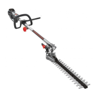
1. Align the upper shaft locking button (a) with the
locking hole of the lower shaft (12) (Fig. 1).
2. Slide the upper shaft (8) of the pole hedge
trimmer on to the lower shaft (12).
3. Ensure the upper shaft locking button (a) clicks
into the hole of the lower shaft (12).
Note: Gently pull the upper shaft (8) to ensure the locking button has engaged
correctly into the hole of the lower shaft (12).
4. Once the upper shaft (8) and lower shaft (12)
have locked together tighten the shaft locking
knob (9) in a clockwise direction (Fig. 2).
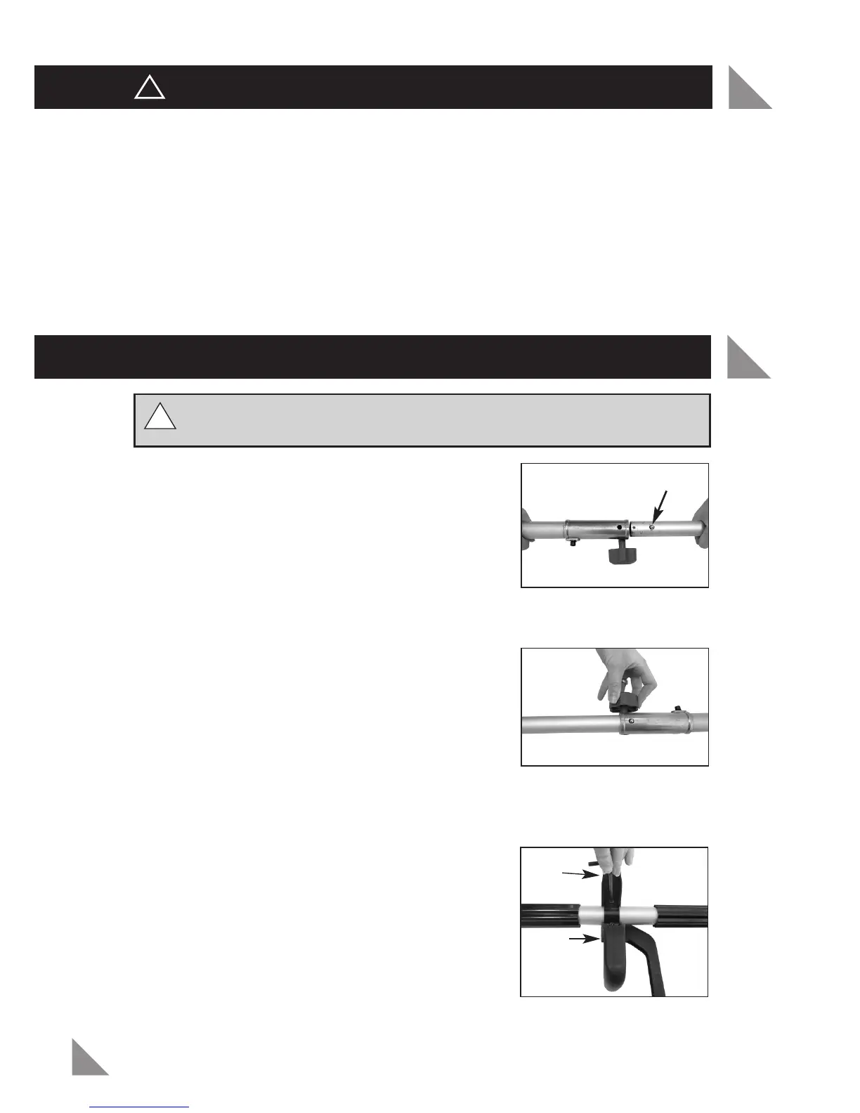
Assembling the adjustable auxiliary handle
1. Locate the adjustable auxiliary D-handle (11) and adjustable auxiliary straight
handle (10) onto the lower shaft (12) between the two safety slides (13).
2. Place the adjustable auxiliary handle bracket (22)
onto the lower shaft (12) and insert the 2 x allen
screws supplied through the holes of the auxiliary
handle bracket (22), adjustable auxiliary D-handle
(11) and adjustable auxiliary straight handle (10).
3. Position the auxiliary handles to a comfortable
position and tighten the two scr
ews with the allen
key (b) provided (Fig. 3).
Note: The allen key is located on the underside of the
auxiliary straight handle.
!
!
Fig. 1
Fig. 2
Fig. 3
a
ASSEMBLY
!!
Allen
key
holder
b
 Loading...