TECHNICAL MANUAL "SE" (PBM753) Revision no. 1 dd. 01/02/2017
P.B.M. S.r.l. via Barella, Z.I. - VIGNOLA ( MO ) ITALIA Tel. + 39 (059) 7705311 Fax + 39 (059) 7705300
http://www.gruppopbm.ite-mail : pbm@gruppopbm.it file: Manuale SE PBM753 GB rev.1.doc
page 2
CHAPTER 1: INTRODUCTION
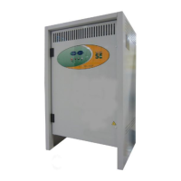
As of September 2016, the “SE” series battery charger has been renewed both externally, with a cabinet
supplied with new colours and a new graphical panel, and technically by adding a new circuit board. The main
technical features are:
• New PBM-753 card at microprocessor, adaptable for three-phase and single phase battery charger.
• SMD technology components.
• Battery charger operating range with rated voltage from 24V to 96V.
• Card powered by mains only (24Vac).
• ON/OFF relay 24VAC/10A with contacts on connector.
• Battery charger functions configuration jumpers set by the user according to requirements.
• New functioning configuration options: 3h Autostart, Safety timer settable at 11h.
• New Equalisation and Floating charge mode.
• 2 calibration modes available: preset mode and adjustable mode.
• ON/OFF button integrated on the card.
• Jumper for manual relay drive.
• Power supply fuse to protect the card (from incorrect setting of battery selection jumpers)
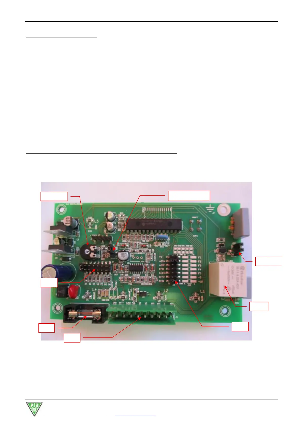
CHAPTER 2: DESCRIPTION OF THE PBM753 CONTROL CARD
The two pictures below show the main components both on the side of components and weldings of the card.
Figure 2a : PBM753 – side of components
J9 : FIX - REG