Pacic Accessory Corporation - 1502 S. Santa Fe Street, Santa Ana, CA 92705
techsupport@pac-audio.com • Voice: (800) 854-3133 • Fax: (800) 832-9722 • www.pac-audio.com
rev. 06-11-2007
Page 1
The OEM-2 may be used in any one of four possible congurations and system types.
1) Replacing a premium factory radio with an aftermarket stereo and use the factory amplier and speakers.
2) Four channel line out converter for adding ampliers to a standard factory speaker system.
3) Adding aftermarket ampliers to a factory premium amplied system (Bose, JBL, etc.).
4) Installing a radio with oating ground speaker outputs to a common grounded speaker system like the early Fords.
The OEM-2 also includes a remote turn-on for ampliers or a power antenna, providing 2 amps at 12 volts when 0.8 volts or greater is applied to the input side. This
is useful for low voltage triggers like those used in Fords or for automatic triggering when audio is present. The output “turn on” is delayed 1 second to prevent turn
on pops.
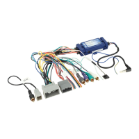
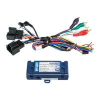
OEM – 2
Universal sound system interface and controller
LF (+) speaker (high power)
White
LF (+) low level output
White/red
LF (+) speaker (low power) White/red LF (+) common gnd. speaker output
White/black
RF (+) speaker (high power)
Gray
RF (+) low level output
Gray/red
RF (+) speaker (low power) Gray/red RF (+) common gnd. speaker output
Gray/black
LR (+) speaker (high power)
Green
LR (+) low level output
Green/red
LR (+) speaker (low power) Green/red LR (+) common gnd. speaker output
Green/black
RR (+) speaker (high power)
Violet
RR (+) low level output
Violet/red
RR (+) speaker (low power) Violet/red RR (+) common gnd. speaker output
Violet/black
RR (–) common
Violet/black
Constant battery Yellow Constant battery
Red
Switched power Red Switched power
Black
Gnd. neg. power Black Gnd. neg. power
Blue
Power antenna turn on Blue Power antenna turn on
Blue/white
Amplifier remote turn on 0.8 v min. Blue/white Amplifier remote turn on 2 amps max.
Orange
Illumination dimming Orange Illumination dimming
Input wiring colors Output wiring colors
1
Connect these wires to an aftermarket radio (+) high power speaker output (typically 20 watts x 4 and higher).
2
Connect these wires to an aftermarket radio (+) low power speaker output. (All stereos up to 20 watts x 4 or when wiring for #4)
3
If the radio is high power (oating ground), connect these wires separately to each of the radio’s speaker (-) wire (do not connect (-) speaker wires together). If the
radio has a common ground speaker outputs, connect these wires together along with the radio’s speaker ground.
4
These wires go directly through to the outputs for convenience of wiring. The red and black wires supply power to the internal low voltage trigger.
5
This wire needs only a minimum of 0.8 volts to supply 12 volts on the blue/white wire on the output side of the OEM-2.
6
For convenience, the positive leads of the RCA are connected internally to these wires.
7
For convenience, the grounds of the RCA are connected internally to these wires. Not used with common grounded speakers.
Note: Some Chrysler/Dodge vehicles with a Innity premium sound system do not need any interface. If the speakers fade and balance correctly with this interface
installed, but you have very little volume, then you do not need this interface.
Pacific Accessory Corporation
Referring to the wire color chart above, connect the speaker outputs of the new radio to the OEM-2, using the positive, solid color, and the negative black-striped
wires for all four channels. On the output side of the OEM-2 connect the solid color wires (+) and the black-striped wires (-) to the factory harness leading to
the factory ampliers. If there are common audio return wires (-) used in the vehicle for either the front and rear channels then connect the negative outputs of
the OEM-2 to them. If there is only one audio return wire for all four channels connect all the black-striped wires to it. Connecting the constant power (yellow),
switched power (red), ground (black), antenna trigger (blue), illumination (orange), and amplier turn on (blue/white) through the OEM-2 simplies wiring to the
vehicle. The output level controls can be adjusted with a small screwdriver.
1) Replace the factory premium radio with an after market radio/deck and retain the use of the factory ampliers and speakers
OEM-2
Pacific Accessory Corporation - Santa Ana, CA 92705
102.7 FM
wht & wht/blk
gray & gray/blk
grn & grn/blk
vio & vio/blk
(-)
(+)
(-)
(+)
(-)
(+)
(-)
(+)
LF
LR
RR
RF
Aftermarket stereo
connect blu/wht to new stereo's remote wire
Factory Amplifier
blu/wht amplifier remote turn on
wht & wht/blk
gray & gray/blk
grn & grn/blk
vio & vio/blk
plug removed from factory stereo
I
n
p
u
t
O
u
t
p
u
t