Do you have a question about the PAC SRK-JW18EH and is the answer not in the manual?
Crucial installation notes and features that are not retained by the kit.
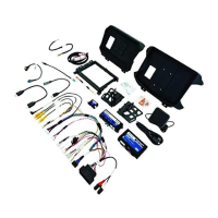
Lists the specific tools required for installation and the components included in the SRK kit.
Step-by-step instructions for removing the factory radio from the vehicle dashboard.
Instructions for removing the glove box assembly to access wiring.
Steps to remove the center console panel to access USB ports and wiring.
Detailed steps for removing door sill trim panels for wire routing.
Instructions for assembling the radio module mounting brackets.
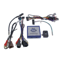
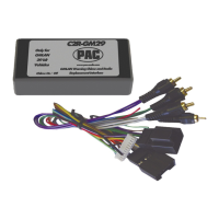
Steps for mounting the CH4A-JW18, PL1, and Stinger radio modules together.
Guide to assembling the HEIGH10 LCD display with its mounting panel.
Detailed steps for connecting the main wiring harness to the Stinger radio module.
Connecting the display power harness and LVDS video cable to the Stinger radio.
Instructions on how to secure the main wire harness using a zip tie.
Steps for connecting the CAN BUS harness to the vehicle's junction blocks.
Routing the GPS antenna and external microphone cables.
Instructions for installing and routing the chime speaker cable.
Connecting the USB retention adapters to the factory USB connectors.
Connecting various harnesses and cables to the radio opening.
Continued steps for routing and connecting in-vehicle harnesses and cables.
Steps for connecting the main 52-pin connector and mounting the Stinger module.
Connecting remaining cables and feeding them to the window switch location.
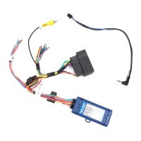
Steps for connecting and mounting the RPA-HD1 module.
Connecting RPA-HD1 module and mounting the radio display assembly.
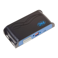
Diagnoses common problems with LED patterns for interface modules.
Instructions for updating firmware for interface modules and the Stinger radio.
Procedure to restore RadioPRO interface modules to factory default settings.
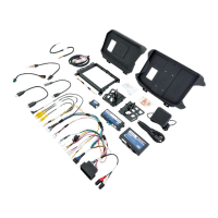
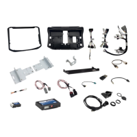
The SRK-JW18EH is a comprehensive radio replacement kit designed for select Jeep Wrangler JL and Jeep Gladiator JT vehicles. This kit integrates climate control retention and includes all necessary modules and cables to maintain essential factory system features such as steering wheel-mounted radio controls, the factory reverse camera, existing USB ports, and AM/FM reception.
The primary function of the SRK-JW18EH is to facilitate the installation of a Stinger HEIGH10™ radio while preserving and enhancing vehicle functionalities. Through data integration with the vehicle, the kit enables the retention and addition of several features:
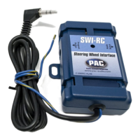
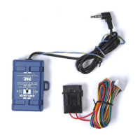
The kit is designed for a plug-and-play installation, minimizing the need for cutting or splicing wires, which simplifies the process. Simplified installation and setup menus allow for direct programming of camera triggers, steering wheel controls, and other settings for both the Stinger HEIGH10™ radio and the CH4A-JW18 interface module.
The SRK-JW18EH does not retain certain factory features:
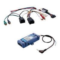
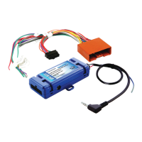
The kit includes a comprehensive set of components for installation:
The kit supports firmware updates for its interface modules (RadioPRO, PL1, HD1) via the RadioPRO PC app. Users can download available updates from www.PAC-audio.com/firmware. The update process involves connecting the interface module to a PC via a micro USB cable and using the "Update Firmware" function in the app. Firmware updates for the Stinger radio and PAC Application APK are detailed in the Installer Setup Manual for the Stinger radio unit.
The RadioPRO interface module can be restored to factory default settings by pressing and holding the programming button on the side of the module until the status LED blinks red. Releasing the button while the LED is blinking red will perform the reset, restoring all settings to factory defaults.
The manual provides LED diagnostics for the CH4A-JW18 Interface Module, RPA-HD1 Camera Module, and PL1 Adapter Module to assist in troubleshooting. Common issues addressed include:
Technical support is available via email at support@PAC-audio.com, by phone at 866-931-8021, and internationally at 727-592-5991.
| Brand | PAC |
|---|---|
| Model | SRK-JW18EH |
| Category | Automobile Accessories |
| Language | English |