SCREWS
8
SPNE 190913-24
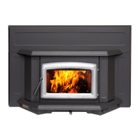
Full Flue Liner (Required in Canada)
Fig #2
This replace insert must be installed with a continuous liner
of 6” diameter extending from the replace insert to the top of
the chimney. The chimney liner must conform to the class 3
requirements of CAN/ULC-S635, Standard for Lining systems
for Existing Masonry or Factory-Built Chimneys or Vents, or
CAN/ULC-S640, Standard for lining systems for New Masonry
Chimneys.
1) Measure the chimney height from the top of the existing
ue to the oor of the hearth. This will allow extra length
of liner for ashing and rain cap.
2) Feed the stainless steel liner from the top of the chimney,
through the damper area and into the replace cavity.
3) Attach a stove connector to the bottom of the liner, as per
the instructions provided with the chimney liner.
4) Push the Insert into position inside the replace and attach
the connector to the stove collar and secure with screws.
Use the rear adjusting legs to level the Insert.
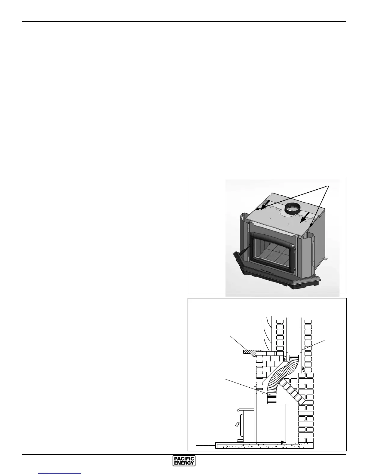
Note: For better access, the top of the casing may be re-
moved (Fig. #3). If it is necessary to get access to the
connector pipe through the ue outlet of the Insert, the
baffle can be removed (see Baffle Removal section).
5) Measure, trim and shape a top ashing to t the existing
chimney ue. Plan for a 1” to 1-1/2” overlap on each side.
Place ashing over top of the liner and seat rmly against
the tile.
6) Screw ashing collar to liner. Caulk gap around ashing
with RTV silicone.
7) Attach a rain cap to the end of the liner. A storm collar
should be used.
Consult your local Dealer about relining your replace chimney.
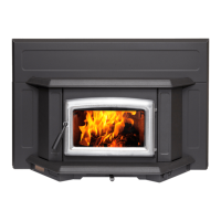
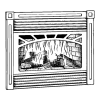
Direct Flue Connection (Only permitted
in USA) Fig #4
1) Measure from the rst chimney ue liner to the top of the
Insert. Allow extra length of liner to insert into ue tile.
2) Feed the stainless steel liner through the damper area
and into the rst chimney ue tile. Seal around pipe.
Note: A clean-out door may be required under local codes,
when a direct ue connection is used. Consult local codes.
3) Push the Insert into position inside the replace and at-
tach the connector pipe to the stove collar. Use the rear
adjusting legs to level the Insert.
Note: For better access, the top of the casing may be removed
(Fig. #3). If it is necessary to get access to the connector
pipe through the ue outlet of the Insert, the baffle can be
removed (see Baffle Removal section).
Into a Factory Built Fireplace
Your Paci c Insert may be installed into a factory built replace
with the following requirements:
1) Inspect your replace for damage or other physical de-
fects. The replace must be in good working condition.
If in doubt about its condition, seek professional advice.
Check for creosote build up or other obstructions inside
the chimney, especially if it has not been in use for some
time. Before installing, clean your chimney system thor-
oughly.
2) A full stainless steel rigid or exible ue liner meeting type
HT requirements (2100°F) per UL1777(U.S.) or ULC S635
(Canada) must be used for both safety and performance.
The liner must be securely attached to the insert ue collar
and the chimney top.
3) The surround must be sealed to the replace front or the
damper area around the chimney liner must be sealed to
prevent room air entering the chimney cavity of the replace.
4) The air ow within and around the replace must not be
altered by the installation of the Insert (i.e. no blockage of
louvers or cooling air inlet or outlet ports). This includes
the circulating air chambers in a steel replace or metal
heat circulator.
5) Alteration of the replace in any manner is not permitted
with the following exceptions:
a: external trim pieces which do not affect the operation
of the replace may be removed and stored on or within
the replace for re-assembly if the Insert is removed.
b: the chimney damper may be removed to install the liner.
Chimney
Flue Liner
6" Stainless Steel
Rigid or Flex Liner
Mantel or
Top Facing
Direct Flue Connection
(USA Only)
Fig. # 3
Fig. # 4