EasyManua.ls Logo

Pacific hydrostar 47906 User Manual

Pacific hydrostar 47906
13 pages
To Next Page IconTo Next Page
Page #1 background imageLoading...
Page #1 background image
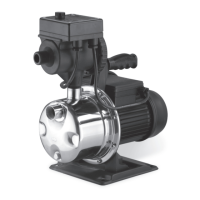
SHALLOW WELL PUMP
1 HP - Stainless Steel
47906
SET UP AND OPERATING INSTRUCTIONS
Visit our website at: http://www.harborfreight.com
Read this material before using this product.
Failure to do so can result in serious injury.
SAVE THIS MANUAL.
Copyright
©
2002 by Harbor Freight Tools
®
. All rights reserved. No portion of this manual or any artwork contained
herein may be reproduced in any shape or form without the express written consent of Harbor Freight Tools.
Diagrams within this manual may not be drawn proportionally. Due to continuing improvements, actual product may
differ slightly from the product described herein. Tools required for assembly and service may not be included.
For technical questions or replacement parts, please call 1-800-444-3353.
Revised Manual 08i, 08k; 09f, 09k
Questions and Answers:

Pacific hydrostar 47906 Specifications

General IconGeneral
BrandPacific hydrostar
Model47906
CategoryWater Pump
LanguageEnglish

Summary

IMPORTANT SAFETY INFORMATION

Safety Alert Symbol Explanation

Explains the safety alert symbol and its meaning for potential hazards.

Hazard Level Definitions

Defines hazard levels: DANGER, WARNING, CAUTION, and NOTICE.

SAFETY WARNINGS AND PRECAUTIONS

General Safety Advice

Read all warnings, save instructions, keep work area clean and lighted.

Personal Safety Practices

Keep children away, use right pump, dress properly.

OPERATIONAL SAFETY GUIDELINES

Personal Protection and Ergonomics

Use eye/ear protection, maintain footing, avoid overreaching.

Maintenance and Care Practices

Keep pump clean, inspect cords, use qualified technicians.

Electrical Safety and Cords

Use proper extension cords, avoid damaged parts, do not install under influence.

SPECIFIC SAFETY AND SPECIFICATIONS

Electrical Safety with Water

Exercise caution with electrical equipment near water; use GFCI outlets.

California Proposition 65 Warnings

Alerts about lead in brass components and cord handling.

Technical Specifications

Lists key operational parameters like voltage, motor speed, flow rate, and pressure.

UNPACKING

Unpacking Procedure

Check for intactness, contact support for missing/broken parts.

INSTALLATION

Water Quality and Suction Lift

Pump water must be clean; total suction lift must not exceed specs.

Installation Components

Install foot valve at bottom of suction pipe, use well seal at top.

INSTALLATION DETAILS

Pipe Requirements and Layout

Minimum 1" diameter pipes, slope off-set line towards well.

Mounting and Safety

Install on rigid platform; use GFCI outlets, keep power lines away from water.

Intake Fitting Caution

Do not insert intake fittings more than 1/2" to prevent pump damage.

OPERATION

Compression Tank Air Pressure

Maintain 26-29 PSI air in compression tank bladder.

Pre-Operation Checks

Ensure intake pipe is submerged; prime pump before first use.

Pump Start and Standby

Plug in, turn on; pump starts automatically and goes to standby mode.

MAINTENANCE

Pre-Maintenance Safety

Disconnect power source before performing maintenance.

Routine Care and Storage

Clean inlet screen, wipe pump, drain for storage, check impeller after storage.

TROUBLESHOOTING

Common Starting and Flow Issues

Solutions for pump not starting, no water, or low water volume.

Performance and Pressure Problems

Covers motor overheating, rapid cycling, tank pressure loss.

TROUBLESHOOTING AND INFORMATION

Prime Retention and Air Issues

Solutions for losing prime, bubbles at outlet, or motor running without pumping.

Pump Shut-off Problems

Addresses causes and solutions for the pump failing to shut off.

Repair and Liability Disclaimer

States repairs should be by certified technicians; buyer assumes all risk.

PARTS LIST

Component Identification

Lists parts with descriptions and quantities for assembly reference.

Serial Number Record

Instruction to record product serial number or purchase date.

ASSEMBLY DRAWING

Pump Component Diagram

Visual diagram showing pump parts with numerical labels for assembly.

PARTS LIST AND ASSEMBLY DRAWING A

Accessory Parts Diagram

Illustrates parts related to Assembly Drawing A, including the compression tank.

LIMITED 1 YEAR / 90 DAY WARRANTY

Warranty Coverage and Limitations

Details warranty periods, exclusions like misuse, and claim process.

Related product manuals