10
Vertical Ports Left Shaft Drive
(When viewed from front)
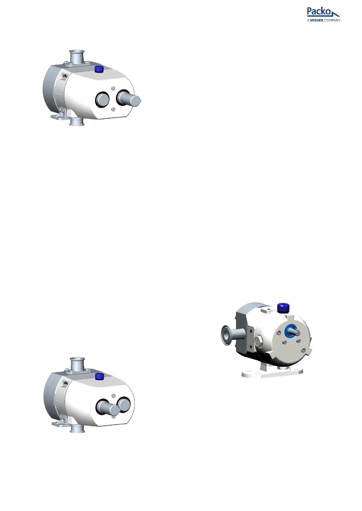
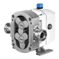
Figure 4 - Vertical ports left shaft drive
• Remove the black hole covers from the
foot location recess and place in a safe
location (33 & 34)
• Push the foot dowel pin (32) (Supplied in
the foot kit) into the un-tapped hole in the
bottom right foot location recess.
• Mate the dowel pin in the bottom right
foot location recess into the dowel pin
hole in the vertical foot (22).
• Push the foot home until the foot face
mates with the foot location recess face.
• Fit the foot bolts (21) (Supplied in the foot
kit) through the feet into the bearing
housing (1) and tighten to the torque
specified in Table 1.
• Repeat the process for the 2
nd
foot using
the top right foot location recess.
• Refit the black hole covers into the left
foot location recesses.
• Remove the breather plug (12) and sight
glass (13) and swap their positions.
Tighten the breather plug and sight glass
to the torque specified in Table 1.
Vertical Ports Right Shaft Drive
(When viewed from front)
Figure 5 - Vertical ports right shaft drive
• Remove the black hole covers from the
foot location recess and place in a safe
location (33 & 34)
• Push the foot dowel pin (32) (supplied in
the foot kit) into the un-tapped hole in the
bottom left foot location recess.
• Mate the dowel pin in the bottom left foot
location recess into the dowel pin hole in
the vertical foot (22).
• Push the foot home until the foot face
mates with the foot location recess face.
• Fit the foot bolts (21) (Supplied in the foot
kit) through the feet into the bearing
housing (1) and tighten to the torque
specified in Table 1.
• Repeat the process for the 2
nd
foot using
the top left foot location recess.
• Refit the black hole covers into the left
foot location recesses.
• Remove the key (29) from the drive shaft
end.
• Remove the 2 bolts (18) from the gear
cover (11) and slide the cover off of the
shaft end, being careful not to damage
the inside of the lip seal on the edges of
the keyway in the shaft. Rotate the gear
cover 180° and re-fit, tightening the 2
bolts. Tighten to the torque specified in
the torque table below.
• Remove the breather plug (12) and the
sight glass (13) and swap their positions.
Tighten the breather plug and the sight
glass to the torque specified in Table 1.
For HP32 and HP34 only
Due to the HP32 and HP34 design only 1 foot is
required for all variations of port and shaft
combinations.
• Remove the black hole covers from the
foot location recess and place in a safe
location (34)
• Align foot mating face on desired bearing
housing boss face to achieve required
shaft and port orientation.