9
• In a clear area allowing access all around
pump and drive for easy servicing.
• With space above for lifting equipment
required.
• With port axis vertical if pump is required
to be self-draining.
All HP & LH pumps are equally suitable for both
directions of rotation.
HP & LH pumps can be rotated to give horizontal
port orientation with top or bottom input shaft
positions or vertical port orientation with left or
right input shaft positions.
See Figure 2, Figure 3, Figure 4, Figure 5, &
Figure 6.
This is achieved with the bolt-on feet and re-
positional gear cover. (Ensure gearbox is drained
of oil prior to gear cover removal)
To change any pump from vertical to horizontal
pipework or vice versa, the correct foot kit needs
to be applied. Foot kits contain all components
required to change orientation.
See below for orientation setup after the packing
feet have been removed.
To orientate the pump for:
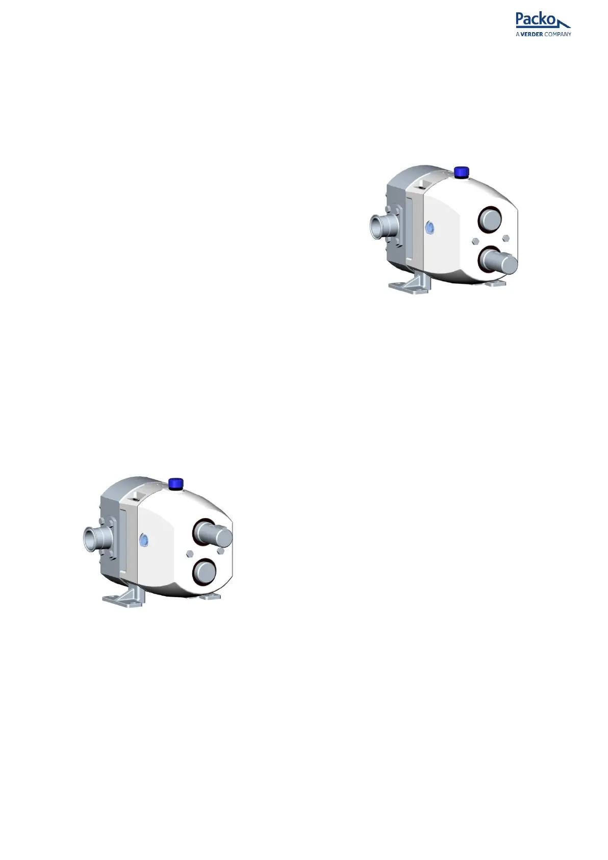
Horizontal Ports Top Shaft Drive
Figure 2 - Horizontal ports top shaft drive
• Remove black hole covers from foot
location recess and place in a safe location
(33 & 34)
• Push foot dowel pin (32) (Supplied in foot
kit) into the un-tapped hole in the bottom
foot location recess.
• Mate dowel pin in bottom foot location
recess into dowel pin hole in horizontal
foot (22).
• Push foot home until foot face mates with
foot location recess face.
• Fit foot bolts (21) (Supplied in foot kit)
through the feet into the bearing housing
(1) and tighten to torque specified in
Table 1.
• Repeat process for 2
nd
foot.
• Refit black hole covers into top foot
location recesses.
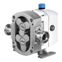
Horizontal Ports Bottom Shaft Drive
Figure 3 - Horizontal ports bottom shaft drive
• Remove the black hole covers from the
foot location recess and place in a safe
location (33 & 34)
• Push the foot dowel pin (32) (Supplied in
the foot kit) into the un-tapped hole in the
top foot location recess.
• Mate the dowel pin in the top foot location
recess into the dowel pin hole in the
horizontal foot (22).
• Push the foot home until the foot face
mates with the foot location recess face.
• Fit the foot bolts (21) (Supplied in the foot
kit) through the feet into the bearing
housing (1) and tighten to the torque
specified in Table 1.
• Repeat the process for the 2
nd
foot.
• Refit the black hole covers into the top
foot location recesses.
• Remove the key (29) from the drive shaft
end.
• Remove the 2 bolts (18) from the gear
cover (11) and slide the cover off of the
shaft end, being careful not to damage
the inside of the lip seal on the edges of
the keyway in the shaft. Rotate the gear
cover 180° and re-fit by tightening the 2
bolts. Tighten to the torque specified in
Table 1.