Table 6 - Rotor clearances (all values in mm)
Axial Clearance: Scimitar and Tri Lobe
• With the pump assembled, the end cover
(122) removed (see 6.1 END COVER), and the
rotors (56) (see 6.2 ROTORS) and rotor case
(1) (6.7 ROTOR CASE) fully secured to the
correct torques.
• Measure the rotor front end clearances (c)
using a depth gauge or feeler gauge and
straight edge.
• If the clearance is incorrect (to Table 6 –
Rotor clearances) remove the rotors (56) (see
6.2 ROTORS).
• Remove the O-rings (31) and shims (30), the
shims are cut to allow them to slide over the
shaft.
• If mechanical shaft seals are fitted take great
care not to scratch, chip or damage the seal
faces.
• Measure the thickness of the shim pack for
each shaft and calculate the thickness of the
shim to add or remove on each shaft to give
the front clearance specified in Table 6 –Rotor
Clearances.
• Shims are available in increments of 0.025
mm (0.001 inch).
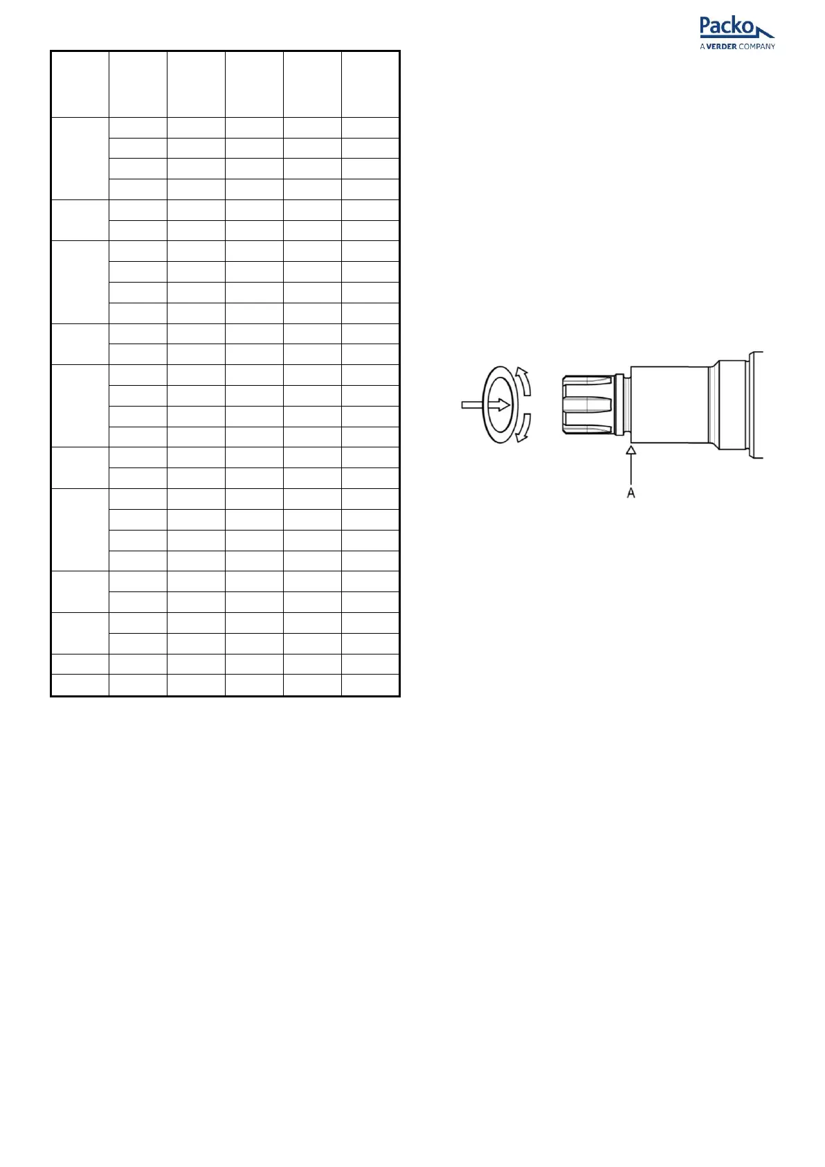
• To fit the shims open them slightly and slide
onto the shaft up to the shoulder (A) (Figure
32).
Note: On HP32 and HP34 tri lobe models splined
shafts are used with shim spacer rings (30a).
Shims are fitted between the shaft shoulder and
shim spacer ring.
Figure 32 - Fitting shims
Note: New shims are not cut; this will need to be
done with scissors prior to fitment if required.
• Fit the shims and retain them with the O-ring
(31).
Note: O-ring not used on HP32 and HP34 models
• Refit the rotors and tighten the retaining bolts
(59) to the correct torque (see 6.2 ROTORS).
Re-check end clearance and re-adjust if
necessary.
Check the condition of the bearings and the pre-
load if any side-to-side movement of the rotors
can be detected or if the radial clearance is
incorrect.
There is no adjustment for radial clearance -
replace the shafts and/or bearings if worn.
Meshing Clearance: Tri Lobe only
For Re-fitting or New Rotors:
• Gear nuts must be tightened to the
correct torque before taking clearance
measurements (see 6.14 BEARING SET-UP