4 RX3i Ethernet NIU
GFK-2419M
Firmware Upgrades
The ENIU uses non-volatile flash memory for storing the
operating system firmware. This allows firmware to be
updated without disassembling the module or replacing
EPROMs.
To install a firmware upgrade, connect WinLoader to the
NIU RS-232 or RS-485 serial port. When connecting
directly to the NIU, there is no need to specify the
Backplane/Slot location. For upgrades to Intelligent Option
modules (the IC695ETM001, for example), which are
performed indirectly via the NIU serial port, you must
specify a backplane/slot location.
Serial Ports
The NIU has two independent, on-board serial ports,
accessed by connectors on the front of the module. These
ports provide serial interfaces to external devices.
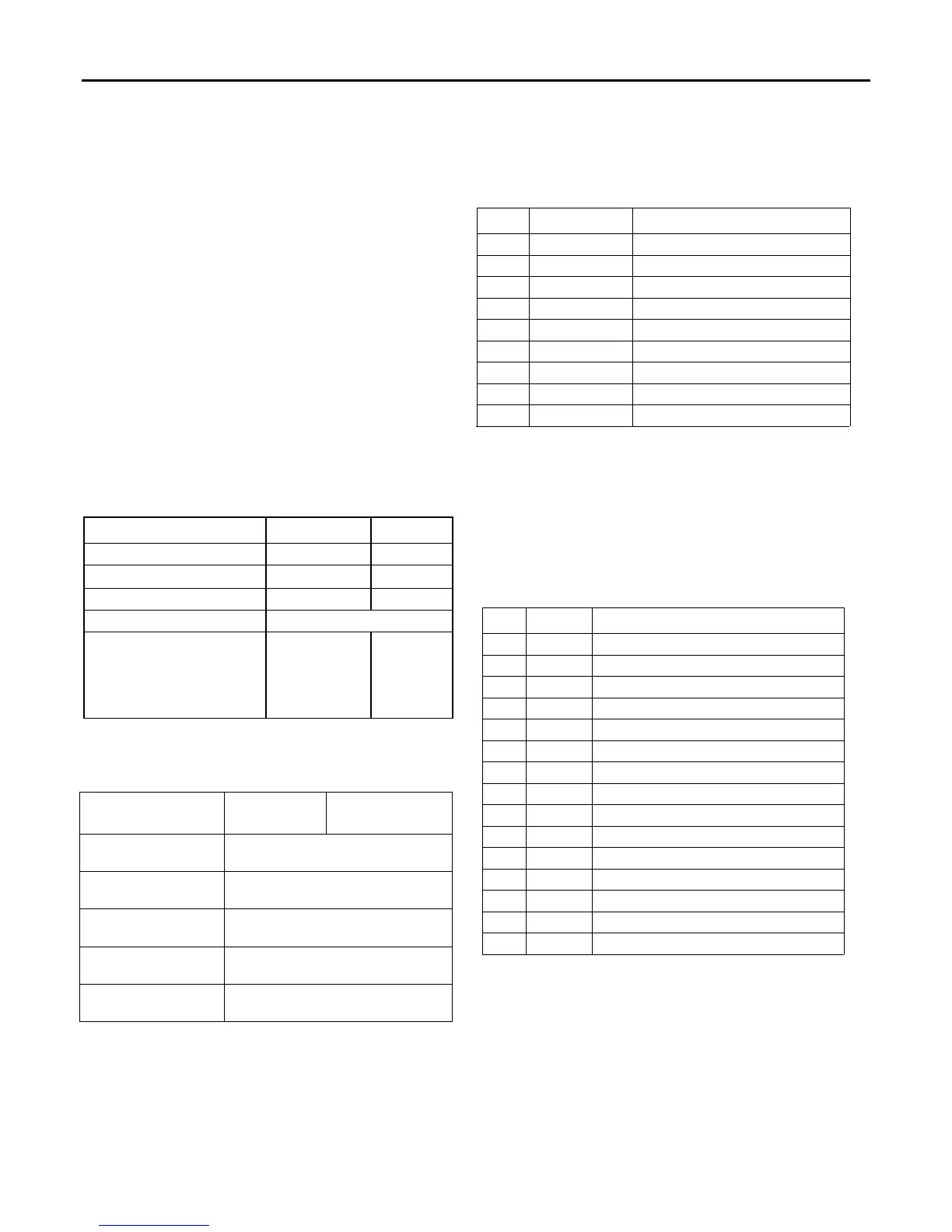
Protocols Supported
Protocol Port 1 Port 2
RTU (slave) Yes Yes
SNP Slave Yes Yes
Serial I/O * Yes Yes
Firmware Upgrade ENIU in STOP/No I/O mode
Message Mode
(C Runtime Library
Functions:
serial read, serial write,
sscanf, sprintf)
Yes Yes
* Modbus Master is supported in application code in Serial
I/O mode.
Serial Port Baud Rates
Protocol
Port 1
(RS-232)
Port 2
(RS-485)
Modbus RTU Slave
protocol
1200, 2400, 4800, 9600, 19.2K,
38.4K, 57.6K, 115.2K
Message 1200, 2400, 4800, 9600, 19.2K,
38.4K, 57.6K, 115.2K
Firmware Upgrade
via Winloader
2400, 4800, 9600, 19.2K, 38.4K,
57.6K, 115.2K
SNP Slave 1200, 2400, 4800, 9600, 19.2K,
38.4K, 57.6K, 115.2K
Serial I/O 1200, 2400, 4800, 9600, 19.2K,
38.4K, 57.6K, 115.2K
Port 1
Port 1 (COM1) is RS-232 compatible. It has a 9-pin,
female, D-sub connector with a standard pin out. This is a
DCE (data communications equipment) port that allows a
simple straight-through cable to connect with a standard AT-
style RS-232 port. The COM1 Active LED provides the status
of serial port activity.
Port 1 RS-232 Signals
Pin Signal Description
1* NC No Connection
2 TXD Transmit Data
3 RXD Receive Data
4 DSR Data Set Ready
5 0V Signal Ground
6 DTR Data Terminal Ready
7 CTS Clear To Send
8 RTS Request to Send
9 NC No Connection
* Pin 1 is at the bottom right of the connector as viewed from the
front of the module.
Port 2
Port 2 (COM2) is RS-485 compatible. Port 2 has a 15-pin,
female D-sub connector. This port supports the RS-485 to
RS-232 adapter (IC690ACC901). This is a DCE port. The
COM2 Active LED provides the status of serial port activity.
Port 2 RS-485 Signals
Pin Signal Description
1* Shield Cable Shield
2 NC No Connection
3 NC No Connection
4 NC No Connection
5 +5VDC Logic Power**
6 RTS(A) Differential Request to Send
7 0V Signal Ground
8 CTS(B‘) Differential Clear To Send
9*** RT Resistor Termination
10** RD(A‘) Differential Receive Data
11 RD(B‘) Differential Receive Data
12 SD(A) Differential Send Data
13 SD(B) Differential Send Data
14 RTS(B) Differential Request To Send
15 CTS(A’) Differential Clear To Send
* Pin 1 is at the bottom right of the connector as viewed from
the front of the module.
** Pin 5 provides isolated +5VDC power (300mA maximum)
for powering external options.
*** Termination resistance for the RD A’ signal should be
connected on units at the end of the line. To make this
termination, connect a jumper between pins 9 and 10
inside the 15-pin D-shell.
 Loading...


