10
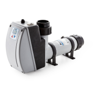
MidiHeat EHA
MA45-32E
ENGLISH
1
4
2
3
5 5
11
9
7
6
8
10
12
13
10
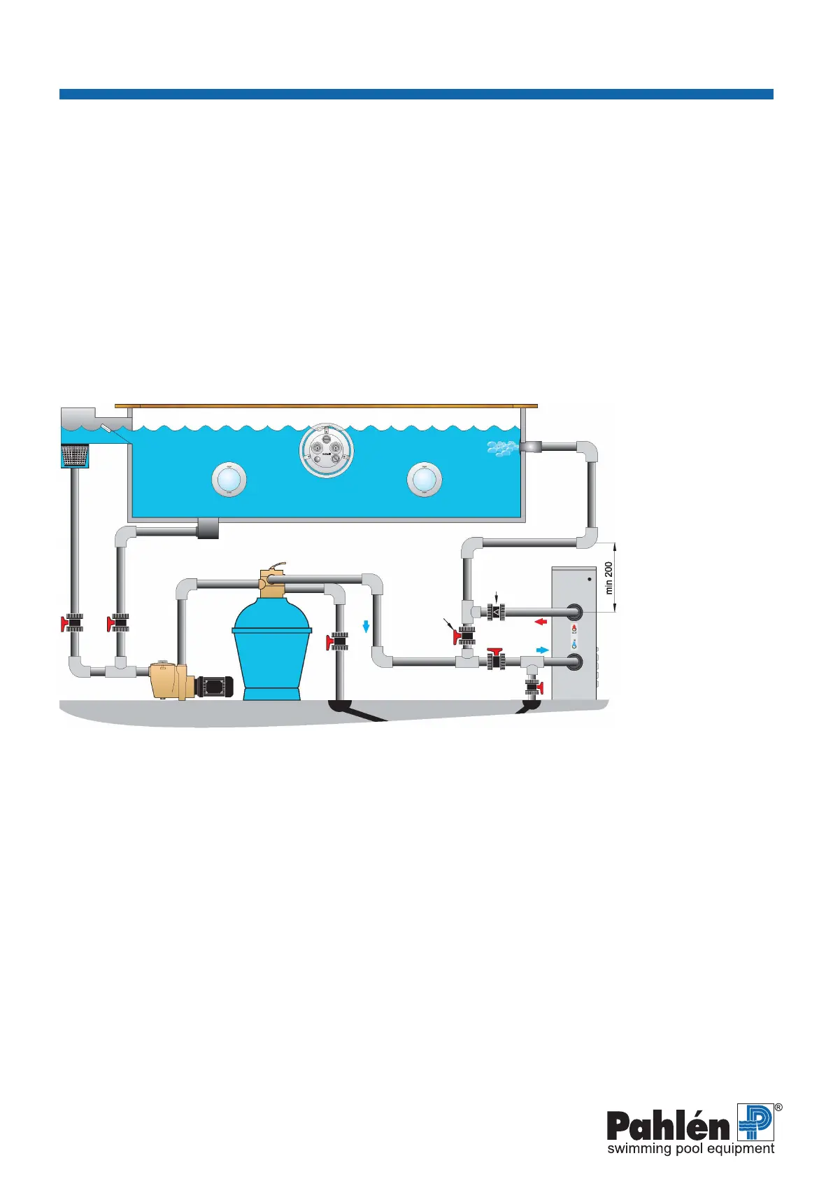
1. Skimmer
2. Maindrain
3. Inlet
4.JetSwim
5. Light
6. Circulationpump
7. Filter
8. MidiHeat
9. Non-returnvalve
10.Drain
11. Bypass valve
12.Shut-offvalve
13. Draining valve
Figure2
Electrical installation
• Theelectricalinstallationmustbeperformedbyanauthorizedelectricianandinaccordancewiththeinstructionsincluded
withtheheater.
• Amainswitchmustbettedbeforealloftheheater’selectricalconnections(L1,L2L3).Thismustbeamulti-poleswitch
thatfullsthedemandsofIEC/EN60335-1sections7.12.2,22.2,24.3.
• Werecommendtheinstallationofaresidualcurrentdevice.
• Connecttheheaterinaccordancewiththeconnectiondrawing,seepages13and14.
• ThecontrolvoltageisconnectedtoconnectionblockL1andNfromasinglephase230VsupplyortoL1andL2froma
3-phase230VsupplywithnoN(neutral).
Notethatthecontrolvoltagemustbeequippedwithseparate5–10Afusesfortheelectricalconnections(L1,L2).
• Theheatermustbeinstalledinsuchawaythatitcannotbeactivatedunlesscirculationpump(sufcientow)isoperational,
i.e.thecontrolvoltagetotheheater’scontactormustbeinterlockedviathepump’scontactor.
• Donotconnecttheheatertoanincorrectpowersource.Contactthelocalelectricalutilityforthecorrectpowersource.
Thevoltagetotheheatermaynotvarybymorethan+5%to-10%withrespecttothemodelandnameplatespecication.
• Ondelivery,theheaterisconnectedfor400V3-phase,seegure4+electricaldrawingpage13,butcanbereconnectedfor
230V3-phase,seegure5+electricaldrawingpage14(appliestoallvariantsexcept72kW).
• Theinputcablingforthecontrolcircuitmustalwaysbefusedfor5–10A.
• Theinputcablingforthecontactorsshallbefusedinaccordancewiththetablefortheoperatingvoltageinquestion,
seegure4or5.
Installation
Piperoutingshallalwaysperformedbeforetheelectricalinstallation.
Positiontheheatersothatthefrontandtopcanbeopened.Installtheconnectionssothattheheatercanbeeasilymovedfor
inspection, cleaning and service.
Anon-returnvalvemustbeinstalledAFTERtheheaterandashut-offvalveBEFOREtheheatertoallowservicingtheheater
withoutneedingtoemptythepool.
Aby-passshouldbeinstalledandadjustedsothattherecommendedowthroughtheheatercanbeattained.
Mounttheheaterontheoor/foundationwithscrews/boltsthroughthefourØ9mmholesinthebottom.
Pipe installation
Connecttheheatertothepoolsystemaccordingtotheowdiagrambelow.Theoutletmustnotbeconnectedtoanyothertype
of tap or connection than those given.
TheelectricheaterhasaG2¾”connectionforgluedattachmentofØ63mmouterdiameterPVCpiping.
NOTE! Do not t a shut-off valve between the heater and swimming pool (t a non-return valve instead).
Mixingofchlorine,acidorsimilarinthepoolwatermustalwaysbeperformedAFTERtheheater,toavoidcorrosion.
 Loading...