Ohjekirja Palax combi M 2004.1 En
12
2
1
23
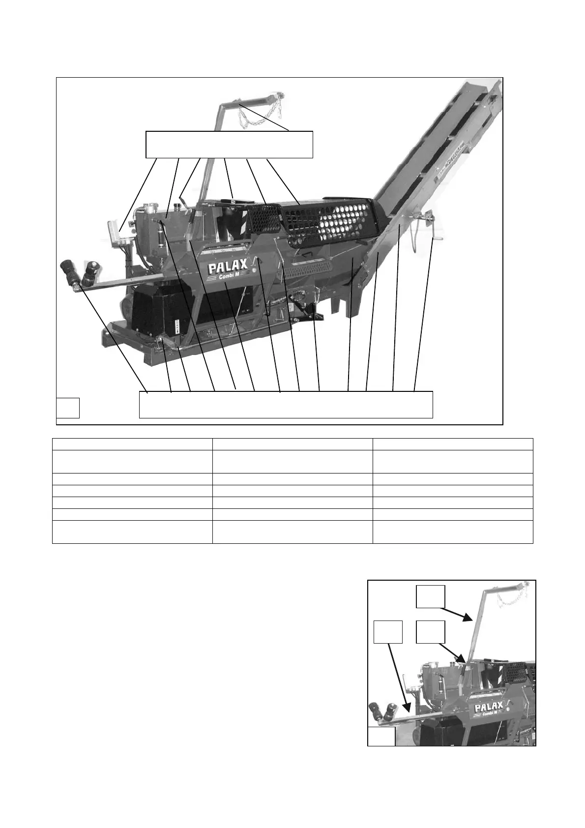
2.3 Main parts of the machine
1. Table extension 8. Log-stop control lever 15. Oil tank
2. Emergency stop lock 9. Splitting blade 16. Disengaging clutch of the
angular gear
3. Emergency stop 10. Debris tray 17. Saw-blade cover
4. High-speed valve lever 11. Conveyor 18. Saw-blade cover net
5. Manual start of splitting motion 12. Supporting wire of conveyor 19. Splitting trough cover net
6. Cross-cut deck 13. Lifting winch of conveyor 20. Conveyor support
7. Splitting blade adjustment lever
(1)
14. Electric motor starter
(1). (only in connection with hydraulic adjustment)
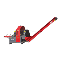
2.4 Assembly of the table extension, Figure 2
Remove the limiting bolt from the end of pipe 3 in the
table extension.
Draw the quick-release lock open and push the pipe
into the pipe in the table.
Fix the limiting bolt (13 mm spanner).
2.5 Assembly of the conveyor support, Figure 2
Place the conveyor support 1 in the sleeve at the
machine frame.
Wrench the screws 2 tight (19 mm spanner).
1
1 2 3 4 5 6 7 8 9 10 11 12 13
14 15 16 17 18 19 20