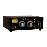
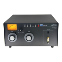
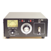
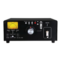
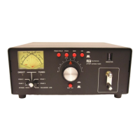
10 Installation cont’d.
1-800-773-7931 W WW.PALST AR . CO M
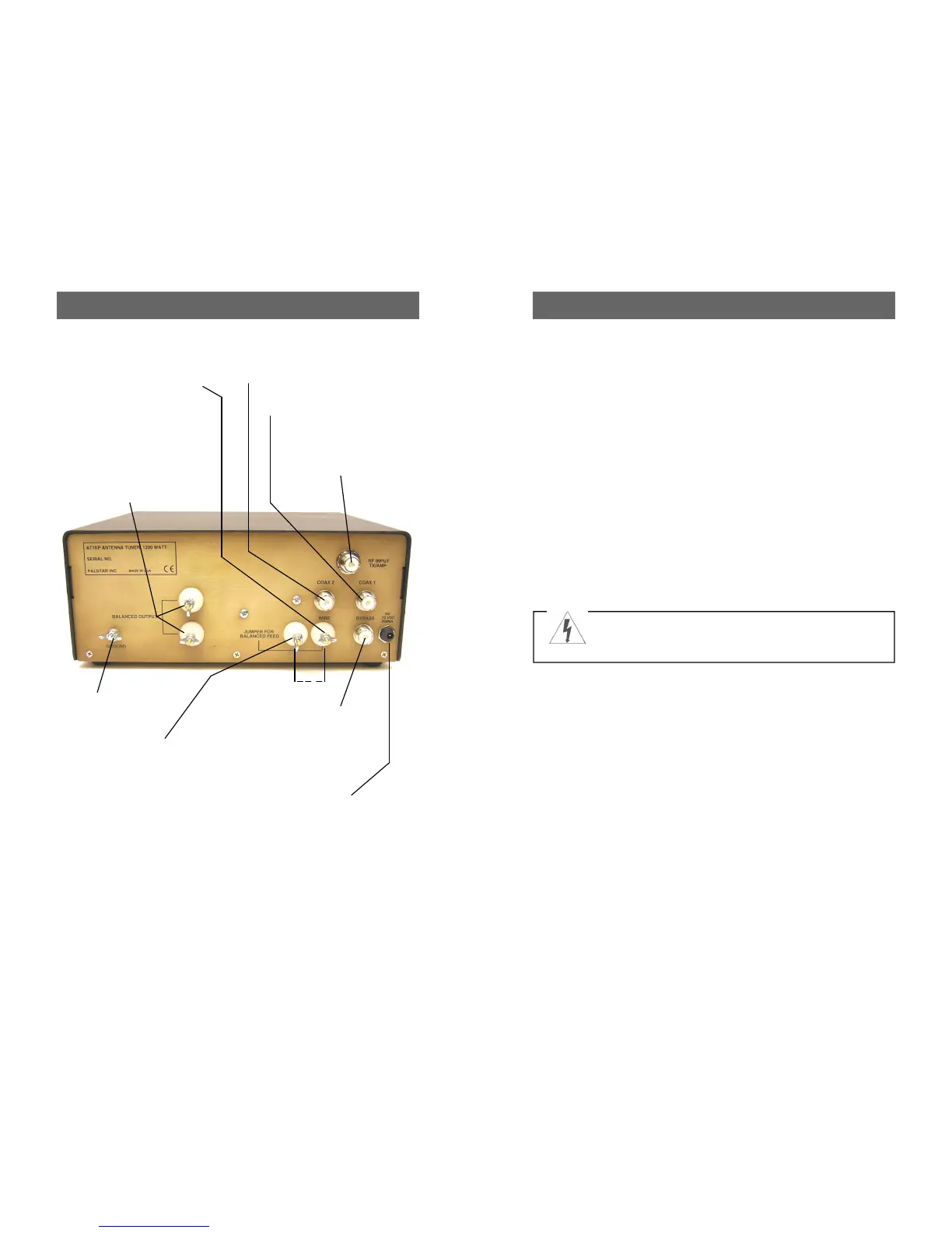
RF INPUT coaxial con-
nector for input from
transmitter or amplifier.
GROUND connector.
BALANCED OUTPUT two
nylon High Voltage post
connectors for output to RF
balanced wire fed antennas.
Copper strap jumper must
be connected between the
END FED WIRE post and
the JUMPER post.
COAX 2 coaxial connector for
output to Antenna Two.
COAX 1 coaxial connector for
output to Antenna One.
BYPASS coaxial connector for
output to dummy load or third
coax output. Bypasses tuner, but
meter circuits are on if AC adap-
tor is connected to jack located
on rear panel.
FIGURE 1: REAR PANEL CONNECTORS
END FED WIRE post connector
for output to a single-wire antenna
(do not use jumper). Ground post
must be connected to good RF
ground.
12 VDC INPUT (2.1 mm
plug, center pin +) for sup-
plied (US only) 12VDC wall
adapter at 200mA to power
the meter lamp, Peak/Peak
Hold function and 160M
inductor relay.
JUMPER post connector. Con-
nect the jumper between this post
and the Wire post when using the
Balanced Output terminals to feed
ladder line.
J
WARNING: Balanced antennas will produce high
RF voltages at the output post connectors. RF
burns may result if touched during transmission.
Installation 7
1-800-773-7931 W WW.PALST AR . CO M
Unpacking
Carefully remove the AT1KP
from the shipping carton and
inspect it for signs of damage. If
any damage is apparent, notify
the transportation carrier or
dealer immediately. We recom-
mend keeping the packing
carton for moving, storing or
reshipping the tuner to us for
repair if required.
Location
Select a location for the AT1KP
that allows the connectors to be
free from any possible contact
with people, pets or objects dur-
ing operation and with unre-
stricted air flow for cooling.
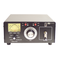
Installation Procedures
Connect a coax cable from your
transmitter to the RF INPUT
connector on the rear panel.
Keep the cable as short as pos-
sible. If you use a linear ampli-
fier, connect your transmitter to
the linear amplifier input and the
linear amplifier output to the
AT1KP. Do not use more than
800 watts average (single
tone) through the tuner.
Connect coax cable(s) from
your antenna to COAX 1 or
COAX 2 connectors on the rear
panel. These connectors are
either direct from the transmitter
or through the tuned circuit de-
pending on the setting of the
DIRECT/TUNED mode switch
on the front panel.
For a balanced feed antenna
connect a balanced feed line the
upper and lower BALANCED
OUTPUT posts, and the sup-
plied jumper strap between the
END FED WIRE post and the
post provided for the jumper
(see pg 10).
If using a single wire antenna,
connect it to the END FED
WIRE post and remove the
jumper strap. When using an
END FED WIRE antenna the
GROUND post must be con-
nected to a good RF ground.
Connect a dummy load to the
BYPASS connector using a
coax cable. This lets you select
the dummy load from the
DIRECT/TUNED mode switch.
Any antenna that does not re-
quire the use of an antenna
tuner may be connected to the
BYPASS connector, if desired.
 Loading...