UNPACKING
Carefully remove the AT2K from the shipping carton and
inspect it for signs of damage. If any damage is apparent,
notify the transportation carrier or dealer immediately.
KEEP THE PACKING CARTON for moving, storing, or
reshipping the tuner to us for repair if required.
LOCATION
Select a location for the AT2K that allows the connectors
to be free from any possible contact with people, pets,
or objects during operation and with unrestricted air
ow for cooling.
INSTALLATION PROCEDURE
Connect a coax cable from your transmitter to the RF
INPUT connector on the rear panel. Keep the cable as
short as possible. If you use a linear amplier, connect
your transmitter to the linear amplier input and the
linear amplier output to the AT2K.
DO NOT USE MORE THAN 1500 WATTS (single tone)
through the tuner.
INSTALLATION
Page 3
+
-
To 12-13.8v
Power Supply
2.1 mm
FEMALE plug
Grey
TRACE ID
Protection
Reverse diode
Red Heat Shrink
cover
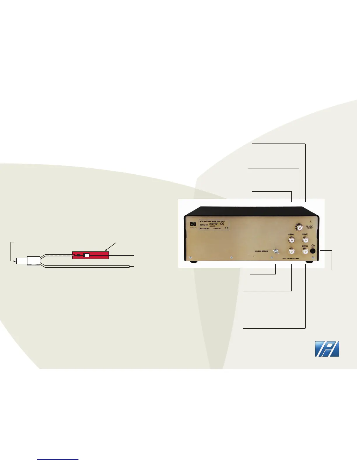
AT2K DC POWER CORD
PALSTAR
REAR PANEL
GROUND post/wing nut
ground connector
COAX-BAL-WIRE
Use this connector
to connect an optional
external 1:1 or 4:1 balun
for balanced or wire feed
antennas
BYPASS coaxial
connector for output
to dummy load or third
coax output. Bypasses
tuner, but meter circuits
are on if AC adapter is
connected to rear panel
12 VDC INPUT
(2.1 mm plug,
center pin +)
12 VDC adapter
200 mA to power
the meter lamp
COAX 2 coaxial connector
for output to Antenna 2
RF INPUT
coaxial connector
for input from transmitter
or amplier
COAX 1 coaxial connector
for output to Antenna 1