WARNING: Balanced antennas will produce high
RF voltages at the output post connectors. RF
burns may result if touched during transmission.
6 Installation
1-800-773-7931 WWW.PALSTAR.COM
Unpacking
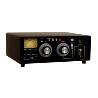
Carefully remove the AT2K from
the shipping carton and inspect
it for signs of damage. If any
damage is apparent, notify the
transportation carrier or dealer
immediately. We recommend
keeping the packing carton
for moving, storing or reship-
ping the tuner to us for repair
if required.
Location
Select a location for the AT2K
that allows the connectors to be
free from any possible contact
with people, pets or objects dur-
ing operation and with unre-
stricted air flow for cooling.
Installation Procedures
(See Figure 1 on next page.)
Connect a coax cable from your
transmitter to the RF INPUT
connector on the rear panel.
Keep the cable as short as pos-
sible. If you use a linear ampli-
fier, connect your transmitter to
the linear amplifier input and the
linear amplifier output to the
AT2K. Do not use more than
1500 watts average (single
tone) through the tuner.
Connect coax cable(s) from
your antenna to COAX 1 or
COAX 2 connectors on the rear
panel. These connectors are
either direct from the transmitter
or through the tuned circuit de-
pending on the setting of the
DIRECT/TUNED mode switch
on the front panel.
Connect a dummy load to the
BYPASS connector using a
coax cable. This lets you select
the dummy load from the
DIRECT/TUNED mode switch.
Any antenna that does not re-
quire the use of an antenna
tuner may be connected to the
BYPASS connector, if desired.
Specifications 15
1-800-773-7931 WWW.PALSTAR.COM
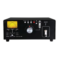
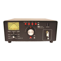
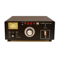
Front Panel Indicators and Controls
Metering Dual movement cross needle power and frequency
compensated coupler
Controls
Input & Antenna Tuning Variable capacitor 400 pF 4.5 KV 6:1 Vernier Drive
Inductance 25 µH roller inductor; 12 ga. wire wound on steatite
ceramic core, silver plated bar/wheel.
Antenna Selector Switch 6 position: Coax 1 tuned and tuner bypass
Coax 2 tuned and tuner bypass
Bypass and balanced antenna
Switch wafers are (3kV rated)
Power Range Switch 2 position 300 W /3000 W
Rear Panel Connectors
RF INPUT SO-239 connector
Coax 1 SO-239 connector
Coax 2 SO-239 connector
Bypass SO-239 connector
Balanced Line COAX (Optional Balun)
End Fed Wire High Voltage Nylon66
TM
terminal post & ground post
12 VDC Input 14mm connector (2.1mm ID, 5.5mm OD, center
positive, 200ma)
Other
Frequency Coverage 1.8 — 54 MHz
Power Maximum 2000 W PEP SSB, 1500 W single tone
Impedance Range 20 to 1500 Ω 160 m to 10 m (assuming resistive
load) Reduce power for lower Z range
Balanced Output 4:1 current type balun EXTERNAL-OPTIONAL
Dimensions 5” H x 14.5” W x 13.5” D (incl. terminals)
Weight 13 lbs.
Materials Chassis and top cover is 11 ga. (.090) aluminum
that has been chem.-film treated. Front Panel
powder coated and epoxy screened.