4 Table of Contents
1-800-773-7931 W WW.PALST AR . CO M
Important safeguards 2
Table of Contents 4
General Description 5
Installation 6
Unpacking 6
Location 6
Installation Procedures 6
Rear Panel Connections 7
Front Panel Description 8
AT4K Schematic 10
Operating Your AT4K 12
Before Operating 12
Tuning 12
Pre-tune Settings 12
Power Specifications 16
Troubleshooting 16
Specifications 17
Meter Board Adjustments 18
Service and Warranty 19
Thank you for purchasing a Palstar AT4K Antenna Tuner. This
antenna tuner has been designed and manufactured to high qual-
ity standards, and will provide reliable operation for many years.
Please carefully read the Owner’s Manual in order to take advan-
tage of the many interesting features that will provide years of en-
joyable amateur
Specifications 17
1-800-773-7931 W WW.PALST AR . CO M
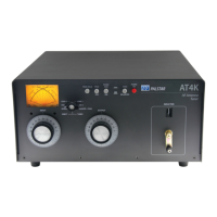
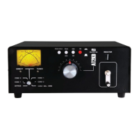
Front Panel Indicators and Controls
Metering Dual movement cross needle power and frequency
compensated coupler
Controls
Input Tuning 480 pF variable capacitor (6kV Peak)
Output Tuning 480 pF variable capacitor (6kV Peak)
Inductance 28 µH roller ceramic body roller inductor wound
with 10 gauge wire
Antenna Selector Switch 6 position:
Coax 1 tuned and tuner bypass
Coax 2 tuned and tuner bypass
Bypass and balanced antenna
Wafer switches are ceramic (7kV/10A)
Power Range Switch 2 position 300 Watts-LO /3000 Watts-HI
Rear Panel Connectors
Coax connectors SO239 connector (silver/gold/TFE)
Balanced Line Dual, High Voltage Nylon66
TM
terminal posts
Other
Frequency Coverage 1.8 — 29.5 MHz
Power 2500 W single tone continuous, 4 kW PEP
Impedance Range See chart of power/complex Z on page 16 for
per band ratings
Balanced Output 1:1 current type Balun at input-Ferrite
Dimensions 6.5”H x 15”W x 16”D (incl. terminals)
Weight 22 lbs.
Materials Chassis parts, brackets and top cover are gold
chem-film coated aluminum (.090” thick). Powder
coating on painted parts.