COPYRIGHT PALSTAR 2011-2014©
limit
limit
limit
stepper
Ant. #3
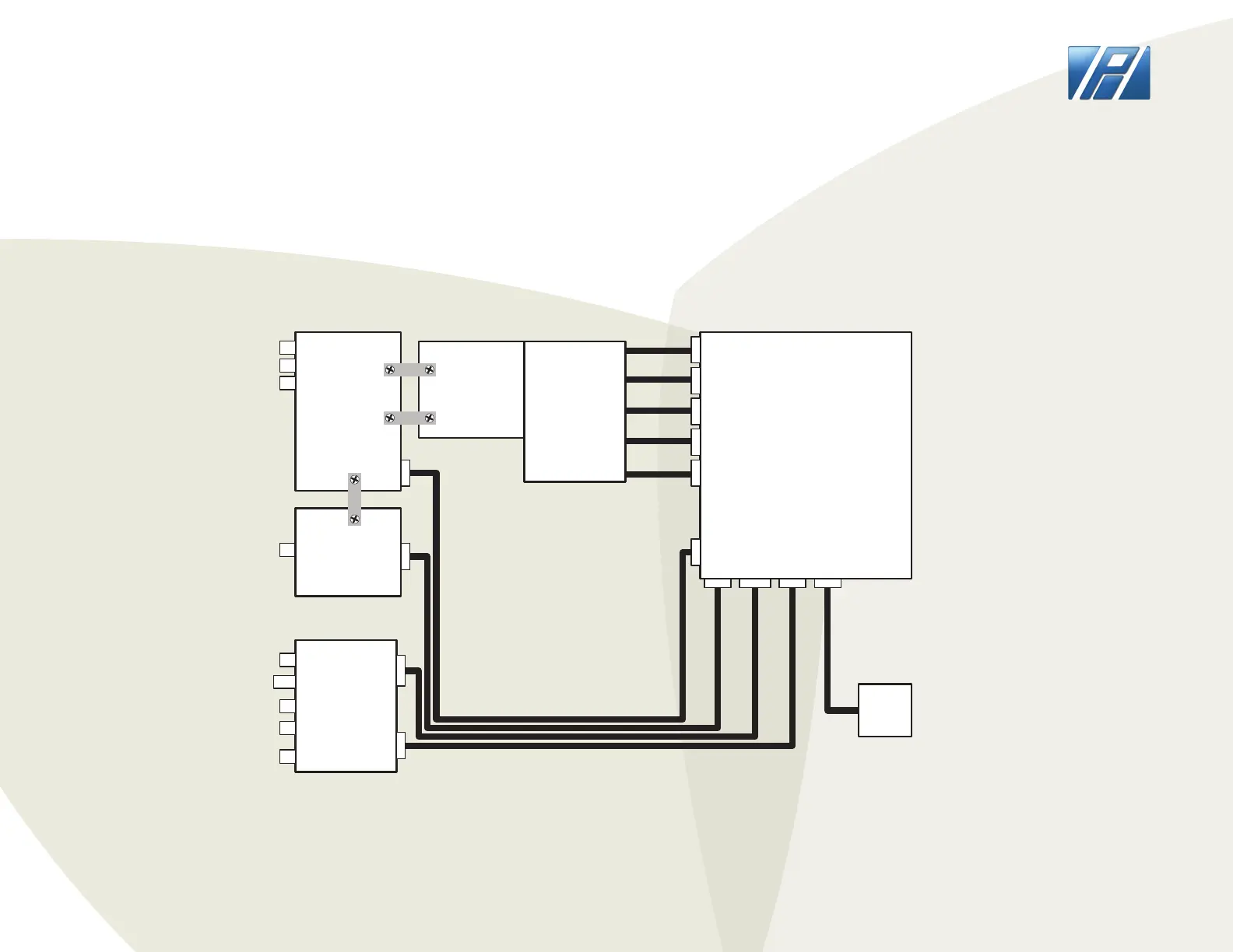
RF Path
PCB
J1
J2
J3
Ant. #1
J4
Pfwd/Prev
Freq. PCB
Ant. #2
Xmtr.
SC1
SC1
Differential
Tee
Network
SC2
SC3
SC2
SC3
Logic / Display/ Buttons
PCB
Interface
PCB
8 pin
6 pin
2 DC
10 pin
4 pin
stepper
8 pin8 pin
Stepper
Motors
4 pin4 pin
P1
DC
J7
J6
J5
RS-232
On/Off
Switch
2 DC2 DC10 pin
8 pin
6 pin
P2
P2
P3
P3 P4
P4
P5
P5 P6
P7
P8
P9
P10
P11
SW1
Program/
Run
J1-J4 = SO-239
J5 = DE-9 Female
SW1 = SPST recessed switch (open = RUN)
J6-J7 = RCA Phono Female
P1 = DC male connector (>5A)
PCB connectors are .1" male 4-10 pins
All mating cable connectors are female
P5-P6 = AMP mate-N-lok
P9-P11 = 4 pin 0.1" spacing
P3 = 6 pin 0.1" spacing
P2, P7-P8 = 8 pin 0.1" spacing
P4 = 10 pin 0.1" spacing
Stepper motors now have different wiring
with no pins having 2 wires. 8 pin connector
is compatible with old 6 pin cables if connect
to pins 2-7.
HF-AUTO SCHEMATIC
PALSTAR
Page 11
 Loading...