Do you have a question about the Panametrics TransPort PT878GC and is the answer not in the manual?
Describes the TransPort features, general system, and theory of operation.
Details the necessary electrical connections for the TransPort unit.
Provides instructions for charging and replacing the PT878GC's internal batteries.
Explains the procedure for powering the PT878GC unit on and off.
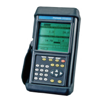
Describes the PT878GC's screen layout and keypad functions for operation.
Details how to access the PT878GC's context-sensitive on-line help system.
Ensures meter capabilities meet application frequencies and minimum pressure requirements.
Locates and prepares the pipe for transducer measurement point installation.
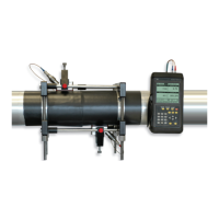
Provides steps for installing the V Series fixture and transducers on the pipe.
Details the installation of PI fixtures and transducers for larger pipe diameters.
Recommends applying DMP dampening material to eliminate short circuit noise.
Guides users on accessing the PT878GC's Program Menu for site-specific data entry.
Details the process of entering transducer type, frequency, and other related parameters.
Explains how to input pipe material, dimensions, and schedule information.
Describes how to specify pipe lining material and thickness for accurate measurements.
Guides on selecting fluid type and entering its sound speed for flow calculations.
Details parameters for signal path, including traverses and spacing for clamp-on transducers.
Covers setting parameters for standard volumetric units and mass flow calculations.
Details setup parameters for Skan/Measure modes, including peak detection and thresholds.
Explains how to specify parameters for general-purpose or standard volume analog inputs.
Guides on setting up analog output parameters for current signal transmission.
Details the setup for digital output parameters like pulse totalizer and frequency.
Enables users to perform mathematical equations on measurements or calculate parameters.
Allows entry and modification of Reynolds Correction, Kinematic Viscosity, and Calibration Factor.
Manages site data files for recall, renaming, printing, transferring, or deletion.
Guides through the process of creating a new site name and configuring it as a template.
Explains how to return to a previously saved site and manage changes.
Provides methods for saving the current site data either immediately or with a new name.
Details the procedure for saving the current site with a new, custom name.
Describes how to update the display with the most current site information.
Explains how to rename an existing site in the Site Manager.
Provides instructions for deleting a selected site from the Site Manager.
Allows adding an explanatory message (up to 30 characters) for any given site.
Details how to print site files using an IR-compatible printer.
Explains how to upload site files to a PC using the infrared interface.
Describes transferring site programming data to a PC in Unicode text format.
Details how to transfer site or meter files from a PC back to the PT878GC via IR.
Allows listing files alphabetically by site name within the Site Manager.
Explains how to list files chronologically by time of creation.
Specifies the type of notation and number of decimal places for measurement display.
Allows selection of parameter presentation format: numeric, line graph, or bar graph.
Enables programming of minimum/maximum values, time interval, and average value display.
Reconfigures a display window with different data sources and measurement units.
Allows display of one or two parameters and customization of soft keys for menu access.
Details how to assign submenus to softkeys for quick access to menus.
Allows review, print, or transfer of files stored in the PT878GC.
Updates the display with the most current information for a highlighted file.
Explains how to upload log, meter, or site files to a PC via infrared.
Details transferring site or meter files from a PC back to the PT878GC over IR.
Provides instructions for deleting a selected file from the File Manager.
Allows listing files alphabetically by name within the File Manager.
Explains how to list files chronologically by time of creation.
Displays model number, software version, and copyright information for the PT878GC.
Guides users to access the Meter Menu for programming global meter settings.
Allows selection of English or Metric units and pressure unit types for measurements.
Enables monitoring of battery status, run time, and conditioning of NiCad batteries.
Provides instructions for setting the meter's current date and time for data logging.
Allows customization of date and time display format (separators, date/time format).
Enables adjustment of screen contrast for comfortable viewing in various environments.
Allows setting a time limit for the PT878GC backlight to remain on before turning off.
Details how to change parameters for PC communication over the wireless infrared interface.
Explains how to clear and reset the forward and reverse totals computed by totalizers.
Supports programming of up to six user tables for non-linear or empirical data.
Enables taking a screen capture in bitmap format for display or storage on a PC.
Guides users to access the Logging Menu for data logging setup and control.
Allows checking the status and memory size of all pending, running, or finished logs.
Provides options to create, copy, rename, delete, print, or transfer logs to a PC.
Enables creation and setup of parameters for a new log, including name and format.
Allows copying parameters of a log, modifying them, and starting the copy.
Provides instructions for renaming a selected log within the Log Manager.
Details the procedure for deleting a selected log from the Log Manager.
Explains how to clear the Log Manager and memory of all logs.
Updates the display with the most current information for a highlighted log.
Details how to print a log file from the Log Manager using an IR printer.
Explains how to upload logs to a PC using the infrared communications port.
Allows pausing, restarting, or ending pending or running logs.
Provides steps to stop a log that is currently pending or running.
Explains how to restart a paused log.
Details the procedure to end a currently pending or running log.
Allows pausing all currently pending or running logs simultaneously.
Provides instructions to restart all paused logs.
Details how to end all currently pending or running logs.
Allows the manager to list logs for all sites, not just the current one.
Enables viewing log data in graphical or spreadsheet formats.
Provides detailed information about a selected log, including state and measurements.
Shows how to view logged data in a graphical format, with options for scale and time.
Details viewing logged data in a spreadsheet format, with options to alter times.
Allows arranging the log list alphabetically (By Name) or chronologically (By Date).
Provides instructions for listing logs alphabetically by log name.
Explains how to list logs chronologically by time of creation.
Guides users to access the Service Menu for performing various functions.
Details printing various data, including site, logs, and user settings, via an IR printer.
Explains the two basic thickness gauge functions and calibration of sound velocity.
Guides on entering material/sound speed and measuring pipe wall thickness.
Describes measuring pipe thickness and displaying it in numeric format.
Shows how to display the acoustic signal graphically for diagnostic purposes.
Provides steps for zeroing transducer offsets using single or dual-point calibration.
Explains how to calibrate pipe material sound velocity for greater accuracy.
Details viewing or changing five parameters for thickness gauge setup.
Enables viewing current diagnostic parameters to aid in troubleshooting.
Covers calibration of analog output zero point and full scale span point.
Details the procedure for calibrating the analog output zero and span points.
Explains input calibration using a current source.
Allows setting parameters affecting the transducer signal, such as Delta-T Offset.
Explains the four measurement modes: Skan, Measure, Integrate, and Correlate.
Details choosing signal type (coded signal or pulses) for Skan detection method.
Enables setting limits for incoming signals to detect errors.
Includes seven tests to ensure the PT878GC is performing properly.
Tests the proper functioning of the PT878GC screen by displaying patterns.
Checks the functioning of the various keys on the PT878GC keypad.
Tests the watchdog timer circuit that automatically resets the meter on software errors.
Enables forcing the meter to transmit in one direction for diagnosing problems.
Captures receive signals to a file for PC analysis by a service engineer.
Uses a stored signal for flow calculations for diagnostic purposes.
Provides battery information for service troubleshooting.
Restores the PT878GC to its original settings, including default parameters.
Explains how to update the meter's operating software using a PC and infrared adapter.
Details the procedure for updating software via the IrOBEX infrared standard.
Describes updating software via the IrCOMM infrared standard.
Lists and explains error messages and suggests actions for isolation and remedy.
Offers a list of diagnostic parameters to aid in troubleshooting flowcell or transducer issues.
Identifies common problems related to gas conditions or pipe installation.
Lists common transducer issues such as leaks, corrosion, internal, or physical damage.
Details specifications for fluid types, pipe sizes, wall thickness, and materials.
Provides specifications for the PT878GC's electronics, including display and memory.
States compliance with EMC Directive and Pressure Equipment Directive.
Lists specifications for transducers, including temperature range and materials.
Details specifications for the optional thickness gauge, including accuracy and range.
Lists specifications for optional features like PC communication and printer.
Provides visual representations of the PT878GC's menu structure.
Details IR communication setup for Windows 2000 and XP operating systems.
Explains IR communication setup requirements for Windows NT4.0.
Guides on IR port installation and configuration for Windows Me/98SE/98/95.
Explains the principles of ultrasonic thickness gauging and factors affecting accuracy.
Provides information on obtaining MSDS for Panametrics Sensing couplants.
| Type | Portable Ultrasonic Flow Meter |
|---|---|
| Fluid Types | Liquids |
| Accuracy | ±1% of reading |
| Display | Backlit LCD |
| Communication | RS-232, USB |
| Measurement Principle | Ultrasonic |
| Pipe Size Range | 0.5 inch (13 mm) and larger |
| Power Supply | Rechargeable battery or AC adapter |
| Outputs | 4-20 mA |
| Enclosure | IP65 |
| Weight | 2.5 kg |
| Memory | Up to 100, 000 readings |