Do you have a question about the Panametrics PanaFlow XMT1000 and is the answer not in the manual?
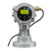
Provides instructions for safe and reliable operation of the XMT1000.
Details wiring requirements for CE marking compliance or installation in high noise areas.
Instructions on inspecting and accounting for all components and packing materials.
Guidelines for locating the flowcell and transmitter, considering access, vibration, and sunlight.
Instructions for making all necessary electrical connections for the XMT1000 flow transmitter.
Provides instructions for programming the various features of the XMT1000 flow transmitter.
Explains the use of the six keys on the magnetic keypad for programming and navigating menus.
Details the default operator and admin passcodes and the importance of changing them.
Provides brief descriptions of standard flow meter terminology used in the manual.
Illustrates menu maps for programming the XMT1000 features, including measurement display and system settings.
Explains how error messages are displayed, including error header and error string.
Explains how to troubleshoot problems with the XMT1000 electronics, flowcell, or transducers.
Details fluid types, transducer types, pipe sizes, data logging, and measurement parameters.
Provides specifications for enclosure, dimensions, display, keypad, I/O, power supplies, and wiring.
Describes the standard Modbus communications protocol and its implementation for the XMT1000.
Lists the Modbus registers, their IDs, descriptions, units, and access levels for the XMT1000.
Explains how to connect a HART communicator to the XMT1000 terminal board with resistive load.
Describes the slide switch used to enable or disable write access to the instrument via HART.
Provides HART output and review menu maps for programming the XMT1000.
Introduces Fieldbus as a digital communication protocol and the XMT1000 FF option.
Covers network configuration, polarity, connection, FISCO, DD file, and default node address.
Details general, physical, communication, user layer, and function block specifications for FF.
Explains how to find FF revision numbers, set passwords, and configure NAMUR NE107 bit map.
Describes how to view measurement values and select units for parameters in the XMIT transducer block.
Details measurement values and parameters common to all three paths in the composite transducer block.
Shows measurement values and parameters for each of the three paths (CHI, CH2, CH3).
Describes the Al block's function for signal conditioning, scaling, filtering, and alarm generation.
Explains the PID function block for control based on a programmable algorithm, useful for flow control.
Details how the flow meter publishes error status and quality parameters on the fieldbus.
Allows users to test the FF implementation without real data by enabling simulation mode.
Provides solutions to common fieldbus problems like communication issues and parameter write failures.
Recommends the DPI620G-FF for local diagnostic capability with the XMT1000 FF option.
| Type | Ultrasonic Flow Transmitter |
|---|---|
| Measurement Principle | Transit-time difference |
| Accuracy | ±0.5% of reading |
| Repeatability | ±0.2% of reading |
| Power Supply | 24 VDC or 100-240 VAC |
| Technology | Ultrasonic |
| Fluid Types | Liquids, gases |
| Outputs | 4-20 mA, Pulse, Alarm |
| Communication Protocols | HART, Modbus |
| Enclosure Rating | NEMA 4X (IP66) |
| Temperature Range | -40°C to 150°C |