6295-6298 ENCLOSED HEAT DETECTOR
- FIRE ALARM SOLUTIONS TECHNICAL DESCRIPTION
6
3.1.2. EXTERNAL LED
One External Indicator (LED) can be connected to the screw terminals E+ and E-:
• E+ Ext. LED, for example Ext. indicator 2218; J2:2 (+)
• E- Ext. LED, for example Ext. indicator 2218; J2:3 (-)
Do not connect an external indicator (LED) to terminals (E+, E-) when the detector is used as intrinsically
safe detector in hazardous (Ex) areas, see 5.2. INTRINSICALLY SAFE INSTALLATION (6295-6296)
on page 9.
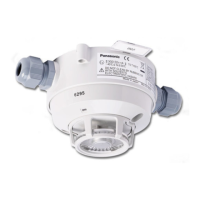
3.2. CONNECTION BOX
The connection box is prepared for required number of compression glands, one, two, or three.
3.3. ZONE LINE INPUT
The conventional detector is connected to a zone line input (for conventional detectors) in the CIE The last unit on the zone line has
an End-of-line device to be connected. The type of end-of-line device is depending on the CIE and the type of zone line input.