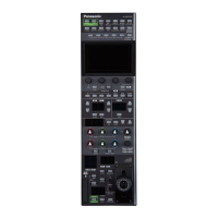
Connections
Set the connection setting to “Serial” or “LAN” in the [CONNECT SETTING] menu.
1
1 / 1
TRACKING
CAMERA
RP
IP SET
CONNECT
SETTING
MANUAL
IP SET
AUTO
IP SET
2 3 4 5
6
1
2
3
4
5
1 11
CAM SEL
1
DATA SAVE
NO?
CNNCT MD
Serial
DATA LOAD
NO?
CAM1
Serial
CAM3CAM2 CAM4
CAM5 CAM7CAM6 CAM8
CAM9 CAM11CAM10 CAM12
CAM13 CAM15CAM14 CAM16
NON NONNON NON
NON NONNON NON
NON NONNON NON
NONNON NON
CAM01 : AW-HR140
When connecting, observe the following points.
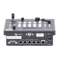
Serial connection
Connect the <SERIAL CONT 1 to 5> connector on this unit to the <RS-422> connector on the AW-HR140/AW-HE130
using a LAN cable (sold separately).
Use a straight cable (category 5e or higher; up to 1000 m (3280 ft) in length) for the LAN cable.
Do not connect a cable for PoE+/PoE++ power supply to the <SERIAL CONT 1 to 5> connector of this unit.
LAN connection
Connect the <IP CONT> connector on this unit to the <LINK / ACT> connector on the AW-HR140/AW-HE130 using a
LAN cable (sold separately).
Use a straight cable (category 5e or higher; up to 100 m (328.0 ft) in length) for the LAN cable (STP).
Configure the camera IP address and port number settings of the connection destinations in [SYSTEM] menu as well.
This unit can be powered using PoE+/PoE++. Use a switching hub with PoE+/PoE++ support.
For details on switching hubs and PoE+/PoE++ injectors that have been verified to support PoE+/PoE++, consult with your
dealer.
- 5 -
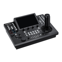
Connecting the Unit to AW-HR140/AW-HE130 Series Cameras
 Loading...