Do you have a question about the Panasonic CQ-DT6930ZE and is the answer not in the manual?
Covers power supply, current consumption, and output power of the unit.
Details AM band frequency range and usable sensitivity.
Details FM band frequency range and usable sensitivity.
Outlines cassette playback system, tape speed, wow/flutter, and S/N ratio.
Detailed list of terminals for the main functional blocks of the device.
Detailed list of terminals for the display unit's interface.
Illustrates the internal block diagram for the main unit's integrated circuits.
Provides the internal block diagram for the tape player mechanism circuitry.
Specifies required voltage, impedance, and output power for alignment.
Detailed steps for calibrating the Dolby Noise Reduction system.
Diagrams showing the physical locations of test points used during alignment.
Lists integrated circuits and transistors used in the tape player.
Lists all diodes used within the tape player section.
Lists all capacitors used within the tape player section.
Lists all resistors used within the tape player section.
Lists all connectors specific to the tape player mechanism.
Details switches and variable resistors for the tape player.
Lists mechanical components, gears, springs, and screws for the tape deck.
Wiring layout for the top surface of the main circuit board.
Wiring layout for the bottom surface of the main circuit board.
Shows the electrical connections for the display unit's components.
Illustrates the electrical connections for the tape player mechanism.
Comprehensive schematic of the tape player's electronic circuitry.
Comprehensive schematics for the main unit and display circuitry.
| Type | Car Receiver |
|---|---|
| Brand | Panasonic |
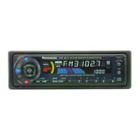
| Model | CQ-DT6930ZE |
| Display | LCD |
| Audio Formats Supported | MP3, WMA |
| Tuner | AM/FM |
| DIN Size | 1 DIN |
| Detachable Face | Yes |
| CD Player | Yes |
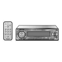
| Remote Control | Yes |
| Playback Formats | CD |
| Power Output | 50W x 4 Channels |