50
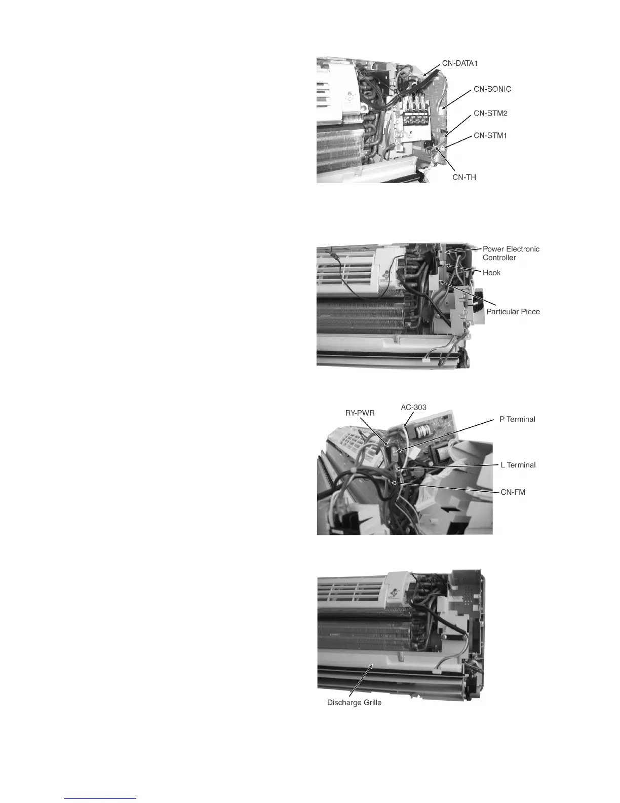
• Release the CN-DATA1 connector. (Fig. 5)
• Release the CN-SONIC connector. (Fig. 5)
• Release the CN-STM2 connector. (Fig. 5)
• Release the CN-STM1 connector. (Fig. 5)
• Release the CN-TH connector. (Fig. 5)
Fig. 5
14.1.3. To remove the Power Electronic Controller
• Release the hook that hold the Particular Piece and pull out
the Power Electronic Controller. (Fig. 6)
• Release the AC-303 connector. (Fig. 7)
• Release the CN-FM connector. (Fig. 7)
• Release the 2 connector P Terminal (BROWN) and L
Terminal (BLACK) at the RY-PWR.
14.1.4. To remove the Discharge Grille
• Pull out the Drain Hose (behind the Discharge Grille) from
outlet to remove the Discharge Grille. (Fig. 8)
Fig. 6
Fig. 7
Fig. 8
 Loading...