Do you have a question about the Panasonic CS-C18HKF and is the answer not in the manual?
| Brand | Panasonic |
|---|---|
| Model | CS-C18HKF |
| Category | Air Conditioner |
| Language | English |
General safety precautions for servicing and operating the air conditioner.
Detailed specifications for the CS-C18HKF and CU-C18HKF models.
Detailed specifications for the CS-C24HKF and CU-C24HKF models.
Key features including e-ion, long piping, and quality/operation improvements.
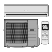
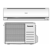
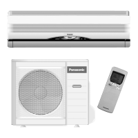
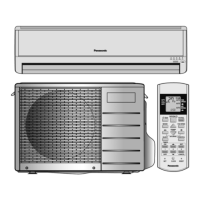
Overview of indoor unit, outdoor unit, and remote control components.
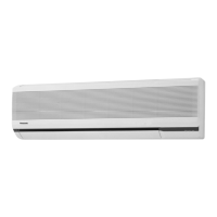
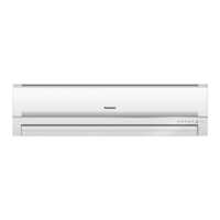
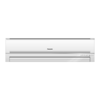
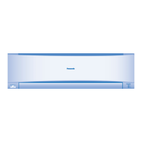
Identification of parts and indicators on the indoor unit.
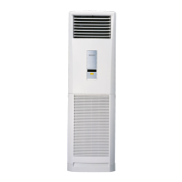
Identification of parts on the outdoor unit.
Identification of buttons and display on the remote control.
Dimensional drawings and measurements for the indoor unit and remote control.
Specific dimensions and installation plate alignment for indoor units.
Dimensional drawings and necessary installation space for outdoor units.
Dimensions and installation space for the CU-C18HK outdoor unit.
Dimensions and installation space for the CU-C24HK outdoor unit.
Schematic of the refrigeration cycle showing key components in indoor and outdoor units.
Functional block diagram illustrating the relationship between indoor and outdoor units.
Wiring diagram for CS-C18HK and CU-C18HK models, including component connections.
Wiring diagram for CS-C24HK and CU-C24HK models, including component connections.
Detailed electronic circuit diagram for the indoor unit and remote control.
Top view layout of the indoor unit's printed circuit board.
Bottom view layout of the indoor unit's printed circuit board.
Top and bottom views of the power printed circuit board.
Layout of indicators on the printed circuit board (top and bottom views).
Guidelines for selecting optimal indoor and outdoor unit installation locations.
Criteria for choosing the best location for the indoor unit.
Criteria for choosing the best location for the outdoor unit.
Diagram showing installation considerations and piping length effects.
Procedures for indoor unit installation, including mounting plate and hole drilling.
Steps for securely mounting the installation plate on the wall.
Instructions for drilling wall holes and inserting piping sleeves.
Steps for piping and connecting the indoor unit to the outdoor unit.
Detailed steps for connecting piping, drain hose, and cables for indoor unit.
Instructions for handling embedded piping during installation.
Procedure for connecting the power cable to the indoor unit.
Instructions for installing the outdoor unit.
Steps for securely mounting the outdoor unit on its base.
Detailed guide on connecting refrigerant piping to indoor and outdoor units.
Procedure for checking for gas leaks and purging air from the system.
Procedure for connecting the power cable to the outdoor unit.
Instructions for insulating pipes to prevent condensation and heat loss.
Description of how to use the cooling operation mode.
Time diagram illustrating compressor and fan operation during cooling.
Explanation of the soft dry operation mode for dehumidification and cooling.
Time diagram for soft dry operation, showing temperature and fan speed.
How to use automatic operation mode and adjust settings.
Methods for controlling indoor fan speed, including manual and auto modes.
Chart showing fan speeds (rpm) for different modes and models.
Details on auto fan speed adjustment based on operation mode.
How to manually adjust the indoor fan speed.
Information on outdoor fan speed control based on temperature.
Controls for adjusting vertical airflow direction automatically and manually.
How auto control adjusts vertical airflow direction.
How manual control adjusts vertical airflow direction.
Controls for adjusting horizontal airflow direction automatically and manually.
How auto control adjusts horizontal airflow direction.
How manual control adjusts horizontal airflow direction.
How to use powerful operation for quick temperature achievement.
How to activate quiet operation for reduced noise levels.
Instructions for setting ON and OFF timers.
How the unit restarts automatically after a power failure.
Description of sounds indicating remote control signal reception.
How to use patrol operation for air quality monitoring and e-ion activation.
Details on patrol sensor control and dirtiness level sensitivity adjustment.
Conditions and timing for e-ion operation activation and duration.
How airflow direction is controlled during various operations.
Sound indications for remote control operations and e-ion status.
Methods for detecting and troubleshooting errors related to the Patrol sensor.
How e-ion operation cleans the air using negative ions.
How airflow direction is controlled during e-ion operation.
How timer controls interact with e-ion operation.
Procedure to check for e-ion system malfunctions.
Error detection methods and troubleshooting for e-ion system issues.
Safety control preventing compressor restarts too quickly.
Mechanism to prevent room humidity buildup by managing compressor start.
Ensures compressor runs for at least 60 seconds for oil circulation.
Manages fan motor start timing to reduce initial current draw.
Protects the indoor heat exchanger from freezing.
Prevents compressor damage from reverse rotation during power interruptions.
Prevents dew formation on the indoor unit discharge area.
How to use the Auto OFF/ON button for operation modes and test runs.
How to select and change the remote control transmission code.
Functions of various buttons on the remote control.
Functions of the SET button for checking codes and adjusting sensitivity.
Function of the CLOCK button to change time format.
Function of the RESET button to restore factory defaults.
Function of the TIMER UP button for LED intensity.
Function of the TIMER DOWN button for display unit change.
Diagnosing issues related to the refrigeration cycle, pressure, and temperature.
How AC conditions affect pressure and electric current during cooling.
Methods to diagnose compressor malfunctions like insufficient compression or locking.
Steps to remove the control board and electronic components from the indoor unit.
Continued steps for removing indoor unit electronic components and connectors.
Further steps for disconnecting connectors and removing control boards.
Final steps for removing the discharge grille and control board.
Steps to remove the indoor fan motor and cross flow fan.
Continued steps for removing the evaporator and fan motor.
Graphs showing thermostat settings vs. intake air temperature for cooling and soft dry modes.
Performance data for CS-C18HKF CU-C18HKF under various conditions.
Cooling characteristic graphs for CS-C18HKF CU-C18HKF.
Graphs showing performance variation with piping length for CS-C18HKF CU-C18HKF.
Cooling characteristic graphs for CS-C24HK CU-C24HK.
Graphs showing performance variation with piping length for CS-C24HK CU-C24HK.
Data on fan speed and air flow for indoor and outdoor fans.
Detailed cooling capacity data tables for CS-C18HKF under various conditions.
Cooling capacity performance data tables for CS-C18HKF.
Graphs of cooling capacity vs. outdoor temperature for CS-C18HKF.
Graphs of power consumption vs. outdoor temperature for CS-C18HKF.
Detailed cooling capacity data tables for CS-C24HKF under various conditions.
Graphs of cooling capacity vs. outdoor temperature for CS-C24HKF.
Graphs of power consumption vs. outdoor temperature for CS-C24HKF.
Exploded view diagram for the indoor unit.
Replacement parts list for the indoor unit, with part numbers and quantities.
Exploded view diagram for the CU-C18HK outdoor unit.
Exploded view diagram for the CU-C24HK outdoor unit.
Replacement parts list for outdoor units CU-C18HK and CU-C24HK.