63
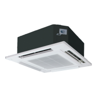
• Connect the indoor unit and the remote controller as shown in the illustration below.
• The remote control cable is non-polar.
• At the time of shipment from the factory, the connector cable used to connect the terminal block and connector CN1 is discon-
nected. When connecting the remote controller wiring and installing the remote controller, be sure to connect the cord to the con-
nector CN1.
• Solder a sheathed PVC cord or cable (0.5 - 2 mm
2
) with specifications among those given below to the remote controller end of
the accessory remote control cable (10 m).
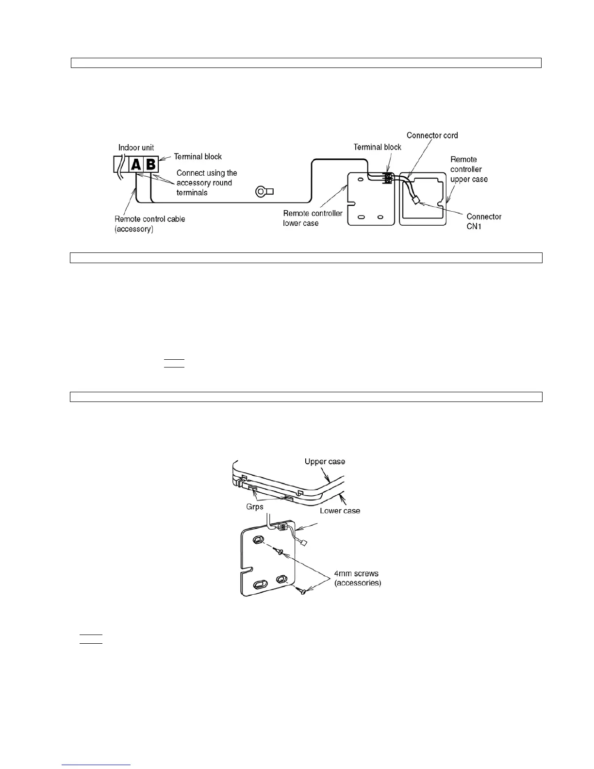
• Remove the remote controller lower case.
(Insert a flat-tipped screw driver or similar 2 to 3 mm into one of the gaps at the bottom of the case, and then twist the screw
driver to open. [Refer to the illustration below.])
Be careful not to damage the lower case.
• Secure the lower case to the wall or outlet box.
(Refer to the illustration at right for the embedded and exposed positions for remote control cable.)
NOTE
- Be sure to use only the accessory screws.
- Do not bend the lower case when tightening the screws.
(If the screws are overtightened, damage may result.)
- Do not remove the protective tape which is affixed to the upper case circuit board.
Remote controller wiring
Extending the remote control cable
* PVC round cabtire cord IEC 502
* 600V PVC-insulated PVC sheathed round cable IEC 227-4
* 600V PVC-insulated PVC sheathed flat cable IEC 227-4
NOTE
The maximum possible length for the remote control cable is 200 m.
Remote controller installation procedure
 Loading...