EasyManua.ls Logo

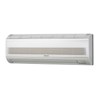
Panasonic CS-MKE12NKU User Manual

Panasonic CS-MKE12NKU
122 pages
To Next Page IconTo Next Page
Page #1 background imageLoading...
Page #1 background image
CU-3KE19NBU (3-room multi unit)
CU-4KE24NBU (4-room multi unit)
CU-4KE31NBU (4-room multi unit)
< Applicable Multi-Outdoor Units >
INDOOR UNIT : CS-MKE7NKU
CS-MKE9NKU
CS-MKE12NKU
CS-MKE18NKU
CS-MKE24NKU
DC INVERTER MULTI-SYSTEM AIR CONDITIONER
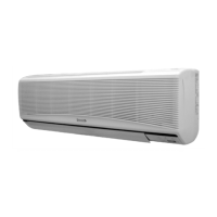
Wall Mounted Type Indoor Unit
CS-MKE7NKU
CS-MKE9NKU
CS-MKE12NKU
CS-MKE18NKU
CS-MKE24NKU
Product Code No.
1 852 360 99
1 852 361 00
1 852 361 01
1 852 361 02
1 852 361 03
Capacity
7,500BTU / h
9,000BTU / h
11,900BTU / h
17,500BTU / h
24,200BTU / h
Indoor Model No.
CS-MKE7NKU
CS-MKE9NKU
CS-MKE12NKU
CS-MKE18NKU
CS-MKE24NKU
A
IR
CO
N
DITIO
NE
R
AIR C
O
N
DITIONER
IMPORTANT
These air conditioners employ new
refrigerant R410A.
Pay special attention when
servicing the unit.
TECHNICAL & SERVICE MANUAL
REFERENCE NO. SM700874

Table of Contents

Other manuals for Panasonic CS-MKE12NKU

Questions and Answers:

Panasonic CS-MKE12NKU Specifications

General IconGeneral
BrandPanasonic
ModelCS-MKE12NKU
CategoryAir Conditioner
LanguageEnglish

Summary

Safety Precautions

General Safety Guidelines

Important safety warnings and precautions to follow during operation and maintenance.

Applicable Multi-Outdoor Units

Indoor/Outdoor Unit Compatibility

Table showing compatibility of indoor units with specific multi-outdoor units.

Operating Range

Temperature Limits for Operation

Defines the operational temperature limits for cooling and heating modes.

Specifications

Indoor Unit Specifications

Detailed technical specs for indoor units: capacity, power, dimensions.

Major Component Specifications

Specifications for key internal components like fan motors and heat exchangers.

Other Component Specifications

Specifications for sensors and their resistance characteristics.

Dimensional Data

Indoor Unit Dimensions

Diagrams and measurements for indoor unit sizes and mounting points.

Refrigerant Flow Diagram

Cooling and Heating Cycles

Schematic diagrams illustrating refrigerant circulation paths.

Performance Data

Air Throw Distance Charts

Graphs showing air throw distance for different flap angles and fan speeds.

Electrical Data

Electric Wiring Diagrams

Wiring diagrams for the indoor unit and its components.

Functions

Operation Functions

Describes modes like Emergency, Auto, SENSOR DRY, and PAM control.

Protective Functions

Details on overload, freeze, and cold-air prevention systems.

Troubleshooting

Pre-Service Precautions

Safety guidelines and initial checks before performing maintenance or repairs.

Self-Diagnostics and Error Codes

Procedure for self-diagnostics and interpretation of error codes.

Unit Checks and Specific Diagnoses

Covers unit checks, serial communication errors, fan motor, and noise issues.

Related product manuals