


P
Pamela MartinAug 7, 2025
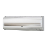
Why does my Panasonic CS-MKS12NKU Air Conditioner stop suddenly?
- AandersonlisaAug 7, 2025
If your Panasonic Air Conditioner unit stops suddenly during operation, it might be due to strong electromagnetic waves nearby, possibly from broadcast stations. To resolve this, try insulating for noise, increasing the distance from the noise source, using shielded wires, or moving the unit away from the noise source.