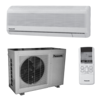
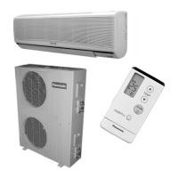
CU-3KE19NBU (3-room multi unit)
CU-4KE24NBU (4-room multi unit)
CU-4KE31NBU (4-room multi unit)
< Applicable Multi-Outdoor Units >
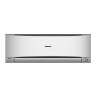
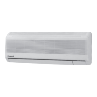
INDOOR UNIT : CS-MKE7NKU
CS-MKE9NKU
CS-MKE12NKU
CS-MKE18NKU
CS-MKE24NKU
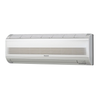
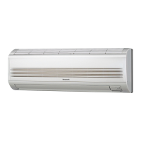
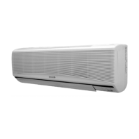
DC INVERTER MULTI-SYSTEM AIR CONDITIONER
Wall Mounted Type Indoor Unit
CS-MKE7NKU
CS-MKE9NKU
CS-MKE12NKU
CS-MKE18NKU
CS-MKE24NKU
Product Code No.
1 852 360 99
1 852 361 00
1 852 361 01
1 852 361 02
1 852 361 03
Capacity
7,500BTU / h
9,000BTU / h
11,900BTU / h
17,500BTU / h
24,200BTU / h
Indoor Model No.
CS-MKE7NKU
CS-MKE9NKU
CS-MKE12NKU
CS-MKE18NKU
CS-MKE24NKU
A
IR
CO
N
DITIO
NE
R
AIR C
O
N
DITIONER
IMPORTANT
These air conditioners employ new
refrigerant R410A.
Pay special attention when
servicing the unit.
TECHNICAL & SERVICE MANUAL
REFERENCE NO. SM700874