Do you have a question about the Panasonic CS-MA95KE and is the answer not in the manual?
Highlights key features like high efficiency, comfort, and improved design.
Details on using the remote control for various operation modes and settings.
Covers Sleep, Powerful, and Economy modes for enhanced comfort and energy saving.
Comprehensive technical data including capacity, airflow, noise, electricals, and dimensions.
Diagrams showing the physical dimensions of the indoor and outdoor units for installation planning.
Visual representation of the unit's refrigeration system, showing component interactions.
Overview of the unit's internal components and their interconnections.
Schematic illustrating the electrical connections for the air conditioner system.
Detailed explanation of cooling operation, including safety controls and fan speed adjustments.
Explains Soft Dry operation, heating mode, and related controls like deicing.
Covers automatic mode selection, sleep, timer, and economy/powerful modes.
Critical safety guidelines for installation, operation, and maintenance to prevent injury or damage.
Instructions on proper usage, precautions, and handling of the air conditioner.
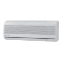
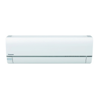
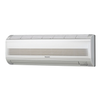
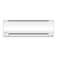
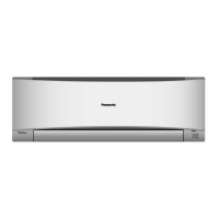
Identification and location of parts on the indoor unit, including filters and indicators.
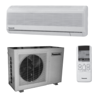
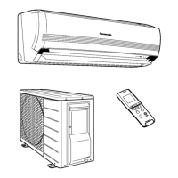
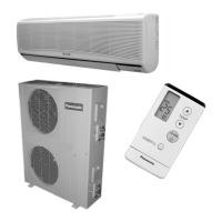
Identification of outdoor unit parts and included accessories like remote control.
Guide to operating the remote control, including button functions and setting the clock.
Steps for preparing the unit before operation, including power connection and filter installation.
Instructions on how to set ON and OFF timers for automated operation.
Details on activating and using the Sleep Mode for comfortable nighttime operation.
Instructions for cleaning the unit, filters, and remote control to maintain performance.
Guidance on periodic inspections, seasonal checks, and preparing the unit for storage.
Addresses common operational questions and potential problems with air conditioner functionality.
Provides tips on auto operation, restart control, and protection against lightning.
Recommendations for optimizing operation to save energy and reduce costs.
Essential safety precautions and a list of required tools for proper installation.
Step-by-step instructions for installing the indoor and outdoor units, including piping and wiring.
Procedures for handling and servicing the 2-way and 3-way valves.
Steps for evacuating the system during installation to ensure proper operation.
Procedure for removing refrigerant from the system before servicing or removal.
Steps for evacuating the system when the air conditioner is being re-installed.
Procedure for balancing refrigerant levels, focusing on valve operations.
Detailed instructions for evacuating the entire refrigeration cycle.
Procedure for charging the system with refrigerant after evacuation or installation.
Disassembly and servicing procedures for the indoor unit's electronic controller and fan motor.
Diagnosing issues related to the refrigeration cycle using pressure, temperature, and current measurements.
Thermostat characteristics, capacity charts, and operation performance graphs.
Diagrams showing the breakdown of parts for CS-MA75KE, CS-MA95KE, CS-MA125KE indoor units.
List of replacement parts for CS-MA75KE, CS-MA95KE, and CS-MA125KE models.
Diagram showing the parts breakdown for the CU-MA195KE indoor unit.
List of replacement parts for the CU-MA125KE indoor unit.
Diagrams showing the parts breakdown for CU-MA185KE and CU-MA245KE indoor units.
List of replacement parts for CU-MA185KE and CU-MA245KE indoor units.
List of electronic components for the controller, identified by symbol and part number.
Schematics illustrating the electronic circuits for various unit models.
Detailed circuit diagram of the wireless remote control unit.
Layout of the indoor unit's printed circuit board, showing component placement (top view).
Layout of the indoor unit's printed circuit board, showing component placement (bottom view).
| Refrigerant | R32 |
|---|---|
| Power Supply | 220 - 240 V, 50 Hz |
| Air Flow Rate | 7.6 m³/min |
| Air Flow (Indoor) | 7.6 m³/min |
| Indoor Unit Noise Level | 19 dB (Low) |
| Noise Level (Indoor) | 19 dB (Low) |