Do you have a question about the Panasonic cs-pa7dkd and is the answer not in the manual?
Details on high efficiency, air quality, comfort, auto restart, and timer settings.
Explains operation modes, fan speed, airflow direction, and temperature settings via remote.
Details on auto switch button, indicator lamps, and basic operation modes.
Explains safety controls, time save, delayed timers, and warm booting functions.
Details on evaporator anti-freezing, fan speed, and airflow direction controls.
Protects the compressor from reverse rotation when power is suddenly switched off.
Details the 2-step overload protector for compressor safety.
Ensures compressor runs for 60 seconds after activation.
Describes anti-freezing operation during Heating Mode.
Details fan and compressor stops based on evaporator temperature for PA7/PA9DKD.
Explains 4-way valve behavior during heating mode for PA7/PA9DKD.
Details cooling/heating capacity, moisture removal, power, airflow, and noise levels.
Covers electrical data, dimensions, weight, piping, and motor specifications.
Details heat exchanger materials, dimensions, refrigerant, and oil specifications.
Lists specifications for capacitors and control devices.
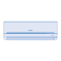
Diagrams and measurements for the indoor unit and installation plate.
Diagrams and measurements for the outdoor unit, including installation space.
Diagram illustrating the refrigeration cycle for PA7DKD and PA9DKD models.
Diagram illustrating the refrigeration cycle for PC7DKD and PC9DKD models.
Schematic block diagram for PA7DKD and PA9DKD indoor and outdoor units.
Schematic block diagram for PC7DKD and PC9DKD indoor and outdoor units.
Detailed wiring diagram for PA7DKD and PA9DKD models, including component connections.
Detailed wiring diagram for PC7DKD and PC9DKD models, including component connections.
Details on Cooling Mode operation, including safety controls and fan speed.
Graph showing intake air temp, evaporator temp, and operation status during cooling.
Explanation of Soft Dry mode, including operation area and safety controls.
Describes automatic fan speed selection during Soft Dry operation.
Graph showing intake air temp, evaporator temp, and operation status during soft dry mode.
Details heating mode operation for PA7DKD and PA9DKD models.
Describes automatic fan speed selection during Heating mode.
Graph showing heat exchanger temp, intake temp, and operation status during heating.
Graph showing indoor piping temp and operation status during normal deicing.
Graph showing outdoor heat exchanger temp and operation status during overload deicing.
Details the first and second determination steps for automatic mode selection.
Explains Air Circulation Mode for PC7DKD and PC9DKD, including heater and airflow.
Describes how the sensor detects and indicates air quality during operation and standby.
Details the process of measuring and updating the sensor resistance reference.
Explains intermittent air quality detection and resistance update when the unit is on standby.
Details the calculation of Rs/MAXR and air quality level determination.
Describes the color coding of the air quality indicator based on pollution level.
Details timing for added operation time based on air pollution levels.
Conditions for resetting the timer based on air quality changes.
Describes how the system reacts to worsening or improving air quality.
Procedure to adjust the sensitivity of the air quality sensor via the remote control.
Steps to activate demo mode by pressing the AUTO button.
Steps to cancel demo mode by pressing the AUTO button.
Control sequences for air quality indicator and ventilator signals during demo mode.
Controlling ventilator operation based on air quality sensor signals.
Lists required devices: Ventilator and Interlocking Unit.
Specifies ventilator activation/deactivation based on air quality and unit status.
Explains how the remote display may not match the unit's actual ON/OFF status.
Details automatic fan speed range from Hi to Slo.
Explains manual fan speed adjustment (Lo, Med, Hi).
Describes automatic louver swing and closing behavior.
Explains manual adjustment and stopping of the airflow direction louver.
Notes on heating mode adjustments and cooling/soft dry mode louver behavior.
Safety warnings and checks before starting the installation process.
Guidelines for selecting the best locations for indoor and outdoor units.
Details on installation steps, necessary parts, and required tools for the process.
Specific guidelines for indoor and outdoor unit placement and clearances.
Specifies maximum allowed piping length and elevation difference between units.
Instructions for cutting pipes, removing burrs, and flaring pipe ends.
Detailed steps for connecting piping on the right side of the indoor unit.
Instructions on tightening flare nuts with torque wrench.
Steps for routing tubing, drain hose, and cables for left side piping.
Hooking the indoor unit onto the installation plate securely.
Ensuring proper tightening of flare nuts with a torque wrench.
Securing piping and connecting cable to the chassis with a clamping cover.
Steps for replacing drain hose, bending piping, and pulling cables.
Details on installing the indoor unit, connecting piping, and cutting/flaring.
Steps for aligning and tightening flare nuts for outdoor unit piping.
Procedure for removing the control board cover and connecting the cable.
Steps to check indoor unit drainage by pouring water into the drain tray.
Guidelines for outdoor unit drainage, especially for heating pump models.
Step-by-step guide for removing and reinstalling the front grille.
Explanation of Auto Operation Mode, Test Run, and Remote Controller sound ON/OFF.
Steps for connecting power supply and preparing the remote control for testing.
Procedure to evaluate performance by measuring air temperatures.
Details shaft positions for shipping, purging, operation, and servicing.
Step-by-step guide for evacuating air from the indoor unit and piping.
Instructions for tightening service port caps to prevent gas leakage.
Detailed steps for pumping down refrigerant before re-installation.
Steps for purging air and charging refrigerant after re-installation.
Procedure for balancing refrigerant levels and discharging excess.
Procedure for evacuating the system during installation.
Procedure for charging the system with refrigerant after evacuation.
Steps for removing the intake grille from the indoor unit.
Steps for removing the front grille, including caps and screws.
Steps for removing the electronic controller cover and lead wires.
Steps for separating the drain hose and drain plate to remove the discharge grille.
Steps for removing the cross flow fan and fan motor.
Instructions for resetting the remote control by shorting terminals.
Diagnosing issues related to the refrigeration cycle, pressure, and temperature.
Checking temperature differences for normal operation and potential issues.
Diagnosing issues based on electric current values compared to specifications.
Troubleshooting based on gas side pressure readings in cooling and heating modes.
Relating air conditioner conditions to pressure and electric current readings.
Methods for diagnosing compressor issues like insufficient compression or locking.
Graphs showing thermostat set points for cooling, soft dry, and heating modes.
Graphs showing cooling capacity, outlet air temp, and current vs. outdoor temp for all models.
Graphs showing heating capacity, outlet air temp, and current vs. outdoor temp for PA models.
Diagram showing all parts of the indoor unit assembly.
List of replaceable parts for PA7DKD and PC7DKD models with part numbers.
List of replaceable parts for PA9DKD and PC9DKD models with part numbers.
Schematic diagram of the electronic controller for PC7DKD and PC9DKD units.
Schematic diagram of the electronic controller for PA7DKD and PA9DKD units.
Circuit diagram of the remote controller's printed circuit board.
| Brand | Panasonic |
|---|---|
| Model | cs-pa7dkd |
| Category | Air Conditioner |
| Language | English |




 Loading...