Do you have a question about the Panasonic CS-PE9RKE and is the answer not in the manual?
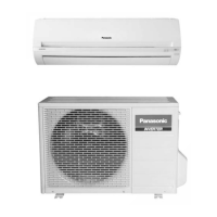
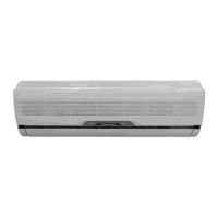
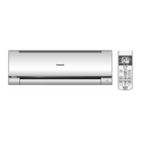
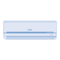
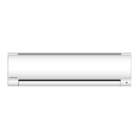
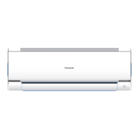
Details on the location of controls and components within the indoor air conditioner unit.
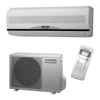
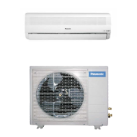
Details on the location of components within the outdoor air conditioner unit.
Explanation of the remote control layout, buttons, and display functions.
Provides detailed measurements for the indoor unit and its remote control.
Provides detailed measurements for the outdoor air conditioner unit.
Illustrates the wiring schematic for the indoor unit, showing component connections.
Illustrates the wiring schematic for the outdoor unit, showing component connections.
Detailed electronic circuit diagram for the indoor unit, showing component layouts and connections.
Detailed electronic circuit diagram for the outdoor unit, showing component layouts and connections.
Diagrams of the main and indicator/receiver printed circuit boards for the indoor unit.
Diagram of the indicator and receiver printed circuit board for the indoor unit.
Diagram of the main printed circuit board for the outdoor unit.
Diagram of the printed circuit board for the CU-UE18RKE outdoor unit.
Diagram of the CPU printed circuit board for the outdoor unit.
Guidance on choosing optimal placement for indoor and outdoor units, considering airflow and environment.
Visual guide for installing both indoor and outdoor air conditioner units.
Instructions for securely mounting the indoor unit's installation plate to the wall.
Procedure for drilling wall holes and installing piping sleeves for indoor unit installation.
Detailed steps for assembling the indoor unit after initial placement, including piping and cable management.
Instructions for connecting power supply and unit connection cables to the indoor unit.
Steps for mounting the outdoor unit and connecting the refrigerant piping.
Procedure for evacuating air from the indoor unit and piping system before refrigerant charging.
Instructions for connecting cables to the outdoor unit and insulating the piping.
Explains basic functions like inverter control, cooling, dry, and heating operations.
Details on indoor and outdoor fan motor speeds and airflow direction control.
Covers timer functions, random auto restart, quiet, and powerful modes.
Details on auto restart, LED indicators, and quiet operation for cooling/dry modes.
Covers quiet operation for heating mode and the powerful mode for quick temperature adjustment.
Details protection mechanisms for all operations, including restart and current controls.
Specific protection controls for cooling and soft dry modes, like freeze and dew prevention.
Protection controls specific to heating operation, covering temperature and overload conditions.
Controls for low temperature compressor oil return, cold draught, and deice operations.
Explains the operation of the Auto OFF/ON button for auto mode, test runs, and setting modes.
Details the functions of various buttons on the remote control, such as SET, RESET, and TIMER.
Guidance on diagnosing issues related to the refrigeration cycle, pressure, and electric current.
Instructions for using the self-diagnosis function to identify and clear error codes.
A comprehensive table of error codes, their causes, and recommended check locations.
Troubleshooting steps for indoor/outdoor communication errors based on self-diagnosis.
Troubleshooting steps for indoor/outdoor capacity rank mismatch errors.
Troubleshooting steps for indoor intake air temperature sensor abnormalities.
Troubleshooting steps for compressor temperature sensor abnormalities.
Troubleshooting steps for outdoor current transformer issues.
Troubleshooting steps for indoor fan motor mechanism lock errors.
Troubleshooting steps for indoor pipe temperature sensor abnormalities.
Troubleshooting steps for outdoor air temperature sensor abnormalities.
Troubleshooting steps for outdoor pipe temperature sensor abnormalities.
Troubleshooting steps for compressor discharge temperature sensor abnormalities.
Troubleshooting steps for outdoor heat exchanger sensor 2 abnormalities.
Troubleshooting steps for unspecified voltage between indoor and outdoor units.
Troubleshooting steps for outdoor heat sink temperature sensor abnormalities.
Troubleshooting steps for outdoor gas pipe temperature sensor abnormalities.
Troubleshooting steps for outdoor liquid pipe temperature sensor abnormalities.
Troubleshooting steps for outdoor fan motor mechanism lock errors.
Troubleshooting steps for issues related to indoor heat exchanger and thermistor errors.
Troubleshooting steps for indoor freeze prevention protection errors.
Troubleshooting steps for 4-way valve abnormalities detected during operation.
Troubleshooting steps for indoor standby unit freezing abnormalities.
Troubleshooting steps for power factor correction protection circuit errors.
Troubleshooting steps for refrigeration cycle abnormalities, including gas leaks.
Troubleshooting steps for compressor rotation failure detected by the position detection circuit.
Troubleshooting steps for outdoor high pressure protection during cooling or soft dry operation.
Troubleshooting steps for IPM overheating protection, including compressor and heat sink issues.
Troubleshooting steps for compressor overheating protection, checking sensors and valves.
Troubleshooting steps for input over current detection, checking refrigerant and PCB.
Troubleshooting steps for DC peak detection related to compressor and PCB issues.
Step-by-step instructions for disassembling the indoor unit, covering grilles, fans, and motors.
Specific disassembly steps for the CS-UE18RKE indoor unit, covering grilles and electronic components.
Instructions for removing the electronic controller from the CU-PE/UE 9/12RKE outdoor unit.
Instructions for removing the electronic controller from the CU-UE18RKE outdoor unit.
Presents performance data for cooling operation under various temperature conditions.
Presents performance data for heating operation under various temperature conditions.
Graphs showing characteristics related to outdoor air temperature during cooling mode.
Graphs showing characteristics related to outdoor air temperature during heating mode.
Data on how piping length affects cooling and heating capacity correction factors.
Detailed exploded view and part numbers for the indoor unit components.
Detailed exploded view and part numbers for the outdoor unit components.
| Ionizer | - |
|---|---|
| Multi-split | Yes |
| Product color | White |
| Hose length (max) | 15 m |
| Dehumidifying capacity | 1.5 l/h |
| Air conditioner functions | Cooling, Heating, Dehumidifying |
| Cooling capacity in watts (max) | 3000 W |
| Cooling capacity in watts (min) | 850 W |
| Heating capacity in watts (max) | 4100 W |
| Heating capacity in watts (min) | 800 W |
| Cooling capacity in watts (nominal) | 2500 W |
| Seasonal efficiency rating (cooling) (SEER) | 5.6 |
| Heating capacity in watts (nominal) (Average heating season) | 3300 W |
| Seasonal efficiency rating (heating) (SCOP) (Average heating season) | 3.8 |
| Wi-Fi | No |
| Indoor unit type | Wall-mountable |
| Indoor unit depth | 214 mm |
| Indoor unit width | 870 mm |
| Indoor unit height | 290 mm |
| Indoor unit weight | 9000 g |
| Indoor units quantity | 1 |
| Cooling airflow (indoor unit) | 702 m³/h |
| Heating airflow (indoor unit) | 768 m³/h |
| Indoor unit noise level (high speed) | 41 dB |
| Current | 16 A |
| AC input voltage | 230 V |
| Design load (cooling) | 2.5 kW |
| Energy efficiency class (cooling) | A+ |
| Power consumption (cooling) (max) | 1020 W |
| Power consumption (cooling) (min) | 250 W |
| Power consumption (heating) (max) | 1180 W |
| Power consumption (heating) (min) | 195 W |
| Annual energy consumption (cooling) | 156 kWh |
| Design load (heating) (Average heating season) | 1.9 kW |
| Energy efficiency class (heating) (Average heating season) | A |
| Annual energy consumption (heating) (Average heating season) | 700 kWh |