62
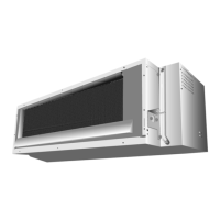
11.3.3.3. Concealed installation
• Only item peculiar to this installation method are given here. See Exposed installation for additional instructions.
Preparation
• Install the unit according to the instructions below. Failure to do so may cause lead to both cooling and heating failure
and the condensation inside the house.
1. Allow enough space between the main unit and ceiling not to obstruct the flow of cool/warm air.
2. Place a partition plate between outlet and inlet sections.
3. Place a partition plate on the right side.
4. Change the upward air flow limit dipswich.
5. Use a movable lattice at the air outlet to allow the adjustment of cool/warm air flow direction.
6. Lattice size should be 70% or more of open rate.
Refrigerant piping
Changing upward air flow limit dipswitch
Change the upward air flow limit dipswitch (SW2-4) to ON to limit the upward air flow.
1. Remove the front grille.
2. Switch the dipswitch (SW2-4) on the PCB in the electrical equipment box to ON.