33
11. Installation Instruction (E9RK and E12RK)
11.1 Select the Best Location
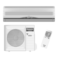
11.1.1 Indoor Unit
Do not install the unit in excessive oil fume area
such as kitchen, workshop and etc.
There should not be any heat source or
steam
near the unit.
There should not be any obstacles blocki
ng the air
circulation.
A place where air circulation in the room is good.
A place where drainage can be easily done.
A place where noise prevention is taken
into
c
onsiderat
ion.
Do not install the unit near the door way.
Ensure the spaces indicated by arrows from the
wall, ceili
ng, fence or other obstacles.
Recommended installation height for ind
oor unit
shall be at least 8 ft (2.4 m).
11.1.2 Outdoor Unit
If an awning is built over the unit to prevent direct
sunli
ght or rain, be careful that heat radiat
ion from
the con
denser is not obstructed.
There should not be any animal or plant which
coul
d be affected by hot air discharg
ed.
Keep the spaces indicated by arrows from
wall,
ceiling, fence or other obstacles.
Do not place any obstacles
which may cause a
sho
rt circuit of the discharged air.
If piping length is over the [piping length
for
addition
al gas], additional refrigerant sh
ould be
adde
d as shown in the tabl
e.
Recommended installation height for outdoor un
it
sho
uld be above the seasonal snow
level.
Example: For E9RKUA
W
If the unit is installed at 32.8 ft (10 m) distance, the
quantity of additional refrigerant should be 1.64 oz
(50 g) .... (32.8 - 24.6) ft x 0.2 oz/ft = 1.64 oz.
((10 -7.5) m x 20 g/m = 50 g).
11.1.3 Indoor/Outdoor Unit Installation
Diagram
Model
Capacity
(Btu/h)
Piping size
Std.
Length
Max.
Elevation
Min.
Piping
Length
Max.
Piping
Length
Additional
Refrigerant
Piping
Length
fo r add.
gas
Gas
Liquid
E9RKUAW 9000
3/8"
(9.52 mm)
1/4"
(6.35 mm)
24.6 ft
(7.5 m)
49.2 ft
(15 m)
9.8 ft
(3 m)
65.6 ft
(20 m)
0.2 oz/ft
(20 g/m)
24.6 ft
(7.5 m)
E12RKUA W 11500
1/2"
(12.7 mm)
1
31
/
32
"
(50 mm)
or m ore
2
9
/
16
"
(
65
m
m
)
or mo
re
8
f
t(2.4
m
)
or m
ore
(Left and right are identical)
Floor / Grade level
Ú
Vinyl tape
•
This illustration is for
explanation purposes only.
The indoor unit will actually face
a different way.
3
1
5
/
1
6
"
(
1
0
0
m
m
)
o
r
m
o
r
e
3
9
3
/
8
"
(
1
0
0
0
m
m
)
o
r
m
o
r
e
3
1
5
/
1
6
"
(1
0
0
m
m
)
o
r
m
o
r
e
1
1
1
3
/
1
6
"
(
3
0
0
m
m
)
o
r
m
o
r
e
It is advisable to
avoid more than 2
blockage directions.
For better ventilation
& multiple-outdoor
installation, please
consult a uthor ized
dealer/specialist.
Installation plate 1
Sleeve (
Ú
)
Bushing-Sleeve (
Ú
)
Bendthepipeas
closely on the wall as
possible, but be careful
that it doesn’t break.
Saddle (
Ú
)
Conduit
(Power supply cord (
Ú
))
Control Board cove r
6
Remote
control
3
Additional drain hose (
Ú
)
Gas side piping (
Ú
)
Conduit
(Connection cable)
Putty (
Ú
)
(Gum Type Sealer)
Installation par ts you
should purchase (Ú)
Vinyl tape (wide) (
Ú
)
• Apply after carrying
out a drainage test.
• To carry out the
drainage test,
and pour water into
remove the air filters
the heat exchanger.
Liquidsidepiping(
Ú
)
Piping direction Do not bend up
drain hose
(Front side)
Right
Rear
Right
bottom
Left
Rear
Left bottom
Left
Insulation of piping connections
Attaching the remote control holder to the wall
• Carry out insulation after
checking for gas leaks and
secure with vinyl tape.
Remote control holder fixing screw s
Remote control holder
5