40
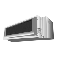
11.3.3.1 Connect the Cable to the Outdoor Unit
1. Remove Top panel.
2.
Remove Control Board Cover (Resin and
Metal).
3.
R
emove Plugs
.
4. Fix the conduit connectors to the knocko
ut
hole
s with lock-nuts, then secure them agains
t
the side p
ane
l.
5.
All wires pass through conduits.
6. Connection cable between indoor un
it and
outdoo
r unit should be UL listed or
CSA
approved 4 conductor wires minimum AWG16
in accordan
ce with local electric code
s.
7.
Wire connection to the power su
pply
(208/2
30V 60Hz) through circuit breake
r.
o
Connect the UL liste
d or CSA approved
wire
s minimum AWG14 to
the terminal
board, and co
nne
ct the other end of the
wires to ELCB / GFCI.
8. Connect the power supply cord a
nd
con
nection cable between indoor un
it and
outdoo
r unit according to the diagram below.
9.
Secure the wire onto the control board wi
th
the holde
r (clamper).
10.
After completing wiring connections, re
attach
the cont
rol board cover (Metal and Resi
n) and
the top panel
to the original position
with the
sc
rews.
11. For wire stripping and connection requirement,
refer to instruction 11.2.5 of indoor unit.
Earth lead wire shall be Yellow/Green
(Y/G) in
colo
ur and shall be longer than other lead wire
s
as sho
wn in the figure for electrical safe
ty in case
of the slippin
g
.
11.3.3.2 Piping Insulation
1. Please carry out insulation at pipe connection portion as mentioned in Indoor/Outdoor Unit Installation
Diag
ram. Please wrap the insulated piping end to prevent water from going inside the piping.
2.
If drain hose or connecting piping is in the room (where dew may form), please increase the insulation
by
using POLY-E FOAM with thickness 1/4" (6 mm) or above.
Control Board
Metal Cover
T
P
el
Power
Supply
Wires
Lock Nuts
Knockout
Holes
Plugs
Side Panel
Connectors
ontrol Board
over (Resin)
Outdoo
nit
1
2
3
1
2
L1
L2
3
lanimreTlanimreT
Indo o
nit
Disconnect
Switch
Field supply
Grounding wire
Grounding wire min AWG16
* Ensure all connecting wire
between indoor unit and
outdoor unit and power supply
cord are installed in individual
conduit.
Power Supply
Single Phase
208/230V 60Hz
min AWG14
208/230V min AWG16
208/230V min AWG16
208/230V min AWG16
WARNING
This equipment must be properly earthed.
Holder
L1 L2 1 2 3
Power
supply
cord
Indoor &
outdoor
connection
cable
Termi n a l
Board
Earth wire
longer than
others AC
wires for
safety
reason
Earth wire
longer than
others AC
wires for
safety
reason