EasyManua.ls Logo

Panasonic CU-E9GKE User Manual

Panasonic CU-E9GKE
72 pages
To Next Page IconTo Next Page
Page #1 background imageLoading...
Page #1 background image
© 2006 Panasonic HA Air-Conditioning (M) Sdn. Bhd.
(11969-T). All rights reserved. Unauthorized copying
and distribution is a violation of law.
Order No. MAC0611054C2
Air Conditioner
CS-E7GKEW CU-E7GKE
CS-E9GKEW CU-E9GKE
CS-E12GKEW CU-E12GKE
TABLE OF CONTENTS
PAGE PAGE
1 Safety Precaution ------------------------------------------------ 2
2 Specifications ----------------------------------------------------- 4
2.1. CS-E7GKEW CU-E7GKE ------------------------------ 4
2.2. CS-E9GKEW CU-E9GKE ------------------------------ 6
2.3. CS-E12GKEW CU-E12GKE--------------------------- 8
3Features------------------------------------------------------------10
4 Location of Controls and Components ------------------11
4.1. Product Overview-----------------------------------------11
5Dimensions--------------------------------------------------------12
5.1. Indoor Unit--------------------------------------------------12
5.2. Outdoor Unit -----------------------------------------------13
6 Refrigeration Cycle Diagram --------------------------------14
7 Block Diagram----------------------------------------------------15
8 Wiring Connection Diagram --------------------------------16
8.1. Indoor Unit--------------------------------------------------16
8.2. Outdoor Unit -----------------------------------------------17
9 Electronic Circuit Diagram -----------------------------------18
9.1. Indoor Unit ------------------------------------------------- 18
9.2. Outdoor Unit----------------------------------------------- 19
10 Printed Circuit Board ------------------------------------------ 20
10.1. Indoor Unit ------------------------------------------------- 20
10.2. Outdoor Unit----------------------------------------------- 22
11 Installation Instruction ---------------------------------------- 23
11.1. Select The Best Location ------------------------------ 23
11.2. Indoor/Outdoor Unit Installation Diagram ---------- 23
11.3. Indoor Unit ------------------------------------------------- 24
11.4. Outdoor Unit----------------------------------------------- 27
12 Operation and Control ---------------------------------------- 30
12.1. Basic Function -------------------------------------------- 30
12.2. Protection Control---------------------------------------- 40
13 Servicing Mode-------------------------------------------------- 44
13.1. Auto OFF/ON Button------------------------------------ 44
13.2. Select Remote Control Transmission Code------- 44
13.3. Remote Control Button --------------------------------- 45

Table of Contents

Questions and Answers:

Panasonic CU-E9GKE Specifications

General IconGeneral
BrandPanasonic
ModelCU-E9GKE
CategoryAir Conditioner
LanguageEnglish

Summary

Safety Precautions

Specifications

CS-E7GKEW CU-E7GKE Specifications

Detailed technical specifications for the CS-E7GKEW CU-E7GKE air conditioner model.

CS-E9GKEW CU-E9GKE Specifications

Detailed technical specifications for the CS-E9GKEW CU-E9GKE air conditioner model.

CS-E12GKEW CU-E12GKE Specifications

Detailed technical specifications for the CS-E12GKEW CU-E12GKE air conditioner model.

Features

Controls and Components Location

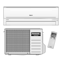
Product Overview

Overview of the indoor unit, outdoor unit, and remote control components.

Indoor Unit Controls and Components

Identification of controls and components on the indoor unit.

Outdoor Unit Controls and Components

Identification of controls and components on the outdoor unit.

Remote Control Overview

Identification of controls and buttons on the remote control.

Dimensions

Indoor Unit Dimensions

Detailed dimensional drawings and measurements for the indoor unit.

Outdoor Unit Dimensions

Detailed dimensional drawings and measurements for the outdoor unit, including installation space.

Refrigeration Cycle Diagram

Block Diagram

Wiring Connection Diagrams

Indoor Unit Wiring Diagram

Detailed wiring connection diagram for the indoor unit's electrical components.

Outdoor Unit Wiring Diagram

Detailed wiring connection diagram for the outdoor unit's electrical components.

Electronic Circuit Diagrams

Indoor Unit Electronic Circuit Diagram

Schematic diagram of the electronic circuits within the indoor unit.

Outdoor Unit Electronic Circuit Diagram

Schematic diagram of the electronic circuits within the outdoor unit.

Printed Circuit Board Layouts

Indoor Unit PCB Layouts

Layout diagrams for the main, power, indicator, and patrol PCBs of the indoor unit.

Indoor Main Printed Circuit Board Layout

Detailed layout of the main printed circuit board for the indoor unit.

Indoor Power Printed Circuit Board Layout

Layout diagram for the power printed circuit board of the indoor unit.

Indoor Indicator Panel Layout

Layout diagram for the indicator panel of the indoor unit.

Indoor Patrol Unit Layout

Layout diagram for the patrol unit of the indoor unit.

Outdoor Unit PCB Layouts

Layout diagram for the main printed circuit board of the outdoor unit.

Outdoor Main Printed Circuit Board Layout

Detailed layout of the main printed circuit board for the outdoor unit.

Installation Instructions

Selecting the Best Installation Location

Guidelines for choosing the optimal location for indoor and outdoor units.

Indoor/Outdoor Unit Installation Diagram

Diagram illustrating the correct placement and spacing for unit installation.

Indoor Unit Installation Procedures

Instructions for mounting the indoor unit, drilling holes, and installing sleeves.

Fixing the Installation Plate

Instructions on how to securely mount the indoor unit's installation plate to the wall.

Drilling Wall Hole and Installing Piping Sleeve

Procedure for drilling the wall hole and installing the piping sleeve with bushing.

Indoor Unit Mounting

Steps for physically installing the indoor unit onto the wall plate, including piping.

Embedded Piping Installation

Steps for installing piping when routed through a wall, including bending, flaring, and insulation.

Connecting Cables to Indoor Unit

Instructions for connecting the indoor and outdoor unit cables, ensuring correct wire colors and terminal numbers.

Outdoor Unit Installation Procedures

Steps for installing the outdoor unit, connecting piping, and flaring.

Installing the Outdoor Unit

Instructions for securely fixing the outdoor unit to its mounting base.

Connecting Piping to Outdoor Unit

Detailed steps for cutting, flaring, and connecting refrigerant piping to the outdoor unit valves.

Evacuating the Equipment

Procedure for removing air and moisture from the refrigeration circuit using a vacuum pump.

Connecting Cable to Outdoor Unit

Instructions for connecting the power supply and inter-unit cables to the outdoor unit.

Operation and Control

Basic Operation Functions

Overview of inverter control and microcomputer functions for optimal comfort and temperature adjustment.

Internal Setting Temperature Adjustment

How the internal setting temperature is determined and updated based on various factors.

Cooling Operation Control

Details on thermostat control for cooling operation, including compressor ON/OFF points.

Soft Dry Operation Control

Details on thermostat control for soft dry operation, including compressor ON/OFF points.

Heating Operation Control

Details on thermostat control for heating operation, including compressor ON/OFF points.

Automatic Operation Mode Selection

How the unit selects operating mode based on temperature and remote control settings.

Indoor Fan Motor Operation Modes

Details on manual and auto fan speed settings and operation patterns.

Outdoor Fan Motor Operation

Description of the outdoor fan motor's operation speed and timing.

Airflow Direction Control

Explanation of automatic and manual control for vertical and horizontal airflow direction.

Vertical Airflow Control

Details on vertical vane angles for different operation modes and manual settings.

Horizontal Airflow Control

Description of manual adjustment for horizontal airflow louvers.

Quiet Operation (Cooling/Dry Mode)

Purpose and control conditions for quiet operation in cooling and dry modes.

Quiet Operation (Heating Mode)

Purpose and control conditions for quiet operation in heating mode.

Powerful Mode Operation

How powerful mode shifts internal setting temperature for quick temperature achievement.

ON Timer Control

Functionality of the ON timer, including early start operation for comfort.

OFF Timer Control

Functionality of the OFF timer to stop the unit at a set time.

Auto Restart Control

How the unit automatically restarts after a power interruption.

Indicator Panel Functions

Explanation of the LED indicators on the unit and their meanings.

Patrol Operation Mode

Purpose and control conditions for patrol operation, monitoring air dirtiness.

e-ion Operation Mode

Purpose and control conditions for the e-ion air purifying system.

Protection Controls

General Protection Controls

Controls that protect the unit during all operation modes, including time delay and current limits.

Time Delay Safety Control

Ensures the compressor does not start for 3 minutes after stopping operation.

30 Seconds Forced Operation

Prevents the compressor from stopping within 30 seconds of starting operation.

IPM (Power Transistor) Protection

Controls to prevent overheating and excessive current in the IPM power transistor.

Compressor Overheating Prevention

Regulates compressor frequency based on discharge temperature to prevent overheating.

Low Pressure Prevention (Gas Leakage)

Detects low pressure conditions indicative of gas leakage and stops operation.

Compressor Tank Temperature Protection

Protects the compressor by monitoring tank temperature rise under specific operating conditions.

Low Frequency Protection Control 1

Adjusts compressor frequency if it operates below a certain limit for an extended period.

Low Frequency Protection Control 2

Sets minimum operating frequency based on various temperature conditions.

Cooling & Soft Dry Operation Protection

Specific protection controls applicable only during cooling and soft dry operations.

Outdoor Air Temperature Protection

Regulates compressor frequency based on outdoor air temperature during cooling/soft dry modes.

Cooling Overload Control

Limits compressor operation frequency when outdoor pipe temperature exceeds a threshold.

Freeze Prevention Control

Stops the compressor if indoor heat exchanger temperature drops too low, resuming when it warms up.

Heating Operation Protection

Specific protection controls applicable only during heating operations.

Intake Air Temperature Protection (Heating)

Controls compressor frequency based on indoor intake air temperature during heating.

Outdoor Air Temperature Protection (Heating)

Regulates maximum current based on outdoor air temperature during heating.

Overload Protection Control (Heating)

Regulates compressor operating frequency based on indoor heat exchanger temperature.

Servicing Modes

Auto OFF/ON Button Servicing

How to activate Auto Operation, Test Run, and Remote Control modes using the Auto OFF/ON button.

Remote Control Transmission Code Selection

Procedure for selecting and storing remote control transmission codes to prevent interference.

Remote Control Button Functions

Details on the functions of various buttons on the remote control, including SET, CLOCK, RESET, TIMER, and TIMER.

Troubleshooting Guide

Refrigeration Cycle Troubleshooting

Diagnosing issues by analyzing gas pressure, air temperature difference, and electric current.

AC Condition vs. Pressure and Current

Table showing how AC conditions relate to pressure and electric current in cooling and heating modes.

Breakdown Self-Diagnosis Function

How to access and interpret error codes using the remote controller for diagnosis.

Error Codes Table

A comprehensive table listing error codes, their meanings, and primary verification locations.

Disassembly and Assembly Instructions

Indoor Unit Component Removal

Procedures for removing the front grille, main electronic controller, and associated components.

Removing the Front Grille

Step-by-step instructions for safely removing the front grille of the indoor unit.

Removing the Main Electronic Controller

Instructions for detaching the control board cover, indicator, and main electronic controller.

Removing the Power Electronic Controller

Steps to remove the power electronic controller, including disconnecting wires and boards.

Removing the Discharge Grille

Instructions for removing the discharge grille, including detaching the drain hose.

Removing the Control Board

Steps for removing the control board by releasing screws and hooks.

Removing Cross Flow Fan and Indoor Fan Motor

Procedures for removing the cross flow fan, indoor fan motor, and associated parts.

Outdoor Unit Electronic Controller Removal

Detailed steps for removing the electronic controller from the outdoor unit, including panel and cover removal.

Technical Data and Characteristics

Operation Characteristics

Graphs showing cooling characteristics (capacity, current, pressure) versus outdoor air temperature.

CS-E7GKEW CU-E7GKE Cooling Characteristics

Cooling performance data plotted against outdoor air temperature for the E7GKE model.

Piping Length Characteristics (Cooling)

Graphs showing cooling performance versus piping length for the E7GKE model.

Heating Characteristics

Graphs showing heating characteristics (capacity, current, pressure) versus outdoor air temperature.

Piping Length Characteristics (Heating)

Graphs showing heating performance versus piping length for the E7GKE model.

CS-E9GKEW CU-E9GKE Cooling Characteristics

Cooling performance data plotted against outdoor air temperature for the E9GKE model.

Piping Length Characteristics (Cooling E9GKE)

Graphs showing cooling performance versus piping length for the E9GKE model.

Heating Characteristics (E9GKE)

Graphs showing heating performance versus outdoor air temperature for the E9GKE model.

Piping Length Characteristics (Heating E9GKE)

Graphs showing heating performance versus piping length for the E9GKE model.

CS-E12GKEW CU-E12GKE Cooling Characteristics

Cooling performance data plotted against outdoor air temperature for the E12GKE model.

Piping Length Characteristics (Cooling E12GKE)

Graphs showing cooling performance versus piping length for the E12GKE model.

Heating Characteristics (E12GKE)

Graphs showing heating performance versus outdoor air temperature for the E12GKE model.

Piping Length Characteristics (Heating E12GKE)

Graphs showing heating performance versus piping length for the E12GKE model.

Sensible Capacity Charts

Tables detailing sensible heat capacity based on indoor and outdoor temperatures for various models.

Exploded Views and Parts Lists

Indoor Unit Exploded View

Diagram showing the exploded view of the indoor unit components.

Outdoor Unit Exploded View

Diagram showing the exploded view of the outdoor unit components.