What causes the F99 (Output Over Current Detection) error in Panasonic Air Conditioner?
- SSara TaylorSep 23, 2025
The F99 error code indicates an Output Over Current Detection. This can be caused by a faulty outdoor unit PCB or a faulty compressor.
What causes the F99 (Output Over Current Detection) error in Panasonic Air Conditioner?
The F99 error code indicates an Output Over Current Detection. This can be caused by a faulty outdoor unit PCB or a faulty compressor.
What does H99 error mean on my Panasonic CU-E9NKD?
The H99 error code on your Panasonic Air Conditioner indicates an indoor freeze prevention protection during cooling or soft dry modes. This can be caused by several factors: an air short circuit at the indoor unit, a clogged air filter, dust accumulation on the heat exchanger, a closed 2/3 way valve, a faulty fan motor, refrigerant shortage (leakage), a clogged expansion valve or strainer, a faulty pipe temperature sensor, or a faulty indoor unit PCB.
What does error code F95 mean on a Panasonic CU-E9NKD?
The F95 error code indicates a cooling high pressure abnormality. This could be due to an air short circuit at the indoor unit, dust accumulation on the indoor unit heat exchanger, a closed 2/3 way valve, a faulty outdoor unit fan motor, excessive refrigerant, a clogged expansion valve or strainer, a faulty outdoor pipe temperature sensor, or a faulty outdoor unit PCB.
Why does my Panasonic CU-E9NKD show H12 (Indoor/Outdoor Capacity Rank Mismatched) error?
The H12 error code on your Panasonic Air Conditioner indicates a capacity rank mismatch between the indoor and outdoor units. This can occur due to wrong models being interconnected, incorrect indoor or outdoor unit PCBs being mounted, defective PCBs, or signal transmission errors caused by incorrect wiring or wire breakage.
What causes the F93 Compressor Rotation Failure in Panasonic CU-E9NKD Air Conditioner?
The F93 error code indicates a compressor rotation failure. This could be due to a disconnected compressor terminal, a faulty outdoor PCB, or a faulty compressor.
What does H32 error mean on my Panasonic CU-E9NKD Air Conditioner?
The H32 error code on your Panasonic Air Conditioner indicates an abnormality with the outdoor heat exchanger temperature sensor 2. This can be caused by a faulty connector connection, a faulty sensor, or a faulty PCB.
What does H28 error mean on my Panasonic CU-E9NKD Air Conditioner?
The H28 error code on your Panasonic Air Conditioner indicates an abnormality with the outdoor pipe temperature sensor. This can be caused by a faulty connector connection, a faulty sensor, or a faulty PCB.
What does H27 error mean on my Panasonic CU-E9NKD?
The H27 error code on your Panasonic Air Conditioner indicates an abnormality with the outdoor air temperature sensor. This can be caused by a faulty connector connection, a faulty sensor, or a faulty PCB.
What does F11 (4-way valve Abnormality) mean for Panasonic CU-E9NKD Air Conditioner?
The F11 error code indicates a 4-way valve abnormality. This can be caused by a connector in poor contact, a faulty sensor, a faulty outdoor unit PCB, or a defective 4-way valve.
What causes the F97 (Compressor Overheating) error in Panasonic Air Conditioner?
The F97 error code indicates compressor overheating. This can be caused by a faulty compressor tank temperature sensor, a closed 2/3 way valve, refrigerant shortage (refrigerant leakage), a faulty outdoor unit PCB, or a faulty compressor.
Key safety instructions and warnings for installation, servicing, and operation.
Detailed technical specifications covering capacity, power, noise, and dimensions for all models.
Details on nanoe-G air purification and use of eco-friendly refrigerants.
Highlights improvements in piping, remote control, quality, operation, and serviceability.
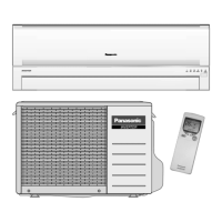
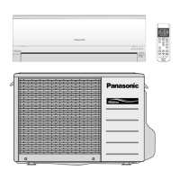
Identifies key components and indicators on the indoor unit.
Overview of the outdoor unit's external parts and design.
Explains the functions and display of the remote control for unit operation.
Provides detailed measurements and diagrams for indoor unit sizes.
Provides detailed measurements and diagrams for outdoor unit sizes.
Illustrates the refrigeration cycle for specific indoor/outdoor unit combinations.
Shows the functional blocks of the electronic control system for specified models.
Diagrams detailing internal wiring connections for indoor units.
Diagrams detailing internal wiring connections for outdoor units.
Detailed schematics of the electronic control circuits for indoor units.
Detailed schematics of the electronic control circuits for outdoor units.
Illustrations of main, indicator, and other PCB layouts for indoor units.
Illustrations of PCB layouts for outdoor units.
Guidelines for choosing optimal placement for indoor and outdoor units.
Step-by-step guide for mounting and connecting the indoor unit.
Procedures for installing the outdoor unit and connecting refrigerant piping.
Covers cooling, heating, and dry modes with thermostat control logic.
Details on indoor fan speed settings and airflow direction adjustments.
Explains Quiet, Powerful, Timer, nanoe-G, Mild Dry, ECONAVI, and AUTO COMFORT modes.
Operation controls specific to multi-split cooling configurations.
Operation controls specific to multi-split heating configurations.
Covers restart, current, IPM, and compressor overheating protection.
Mechanisms for preventing overload, freezing, and dew formation during cooling.
Protection measures for heating, including temperature limits and deice operation.
Using the button for auto operation, test runs, and remote control setup.
Functions for setting, resetting, and managing remote control transmission codes.
Diagnosing issues based on refrigerant pressure and temperature readings.
Interpreting self-diagnosis functions, error codes, and temporary operation.
Detailed troubleshooting steps for communication and sensor abnormalities.
Step-by-step guides for disassembling indoor unit parts like grilles and motors.
Procedures for removing electronic controllers from outdoor units.
Performance data visualized in charts for various operating conditions.
Tables detailing sensible cooling capacity under varying temperatures.
Illustrated exploded views and part numbers for indoor unit components.
Illustrated exploded views and part numbers for outdoor unit components.
| Brand | Panasonic |
|---|---|
| Model | CU-E9NKD |
| Category | Air Conditioner |
| Language | English |


 Loading...